With your schematic completed and approved, the next step is to create a new PCB layout from a schematic. To accurately communicate the schematic design for PCB l layout, a net list and parts list detailing the components and connections are required. This information can change throughout the PCB layout process, making it essential to maintain a bi-directional integration between the schematic and PCB layout to ensure an accurate design. OrCAD X Capture makes it easy to create a new PCB layout from a schematic and automatically sync files to improve efficiency and communication.
This quick how-to will provide step-by-step instructions on how to create a new PCB layout from a schematic in OrCAD Capture.
To follow along, download the provided files above the table of contents.
How-To Video
 Open in New Window
Configuring the Design Sync
Step 1: Open the provided design in OrCAD X Capture.
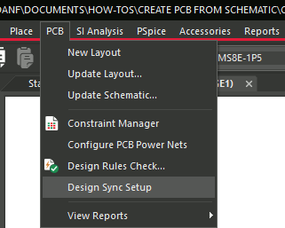
Step 2: Select PCB > Design Sync Setup from the menu. The Design Sync Setup window opens. Here you can configure settings to create a PCB layout.
Step 3: In the text field for Layout Folder, enter allegro to save the layout files in a subfolder of the current design folder with that title.
Note: You can use the ellipsis to browse for a folder, but this will change the path to a complete file path instead of a relative path. Avoid spaces in the folder name. If there are spaces in the complete file path, the layout file may not be generated properly.
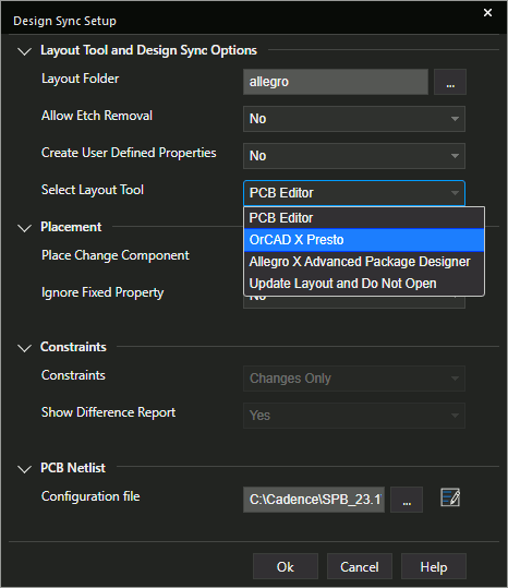
Step 4: Select OrCAD X Presto from the Select Layout Tool dropdown.
Note: Other tools can be selected from this dropdown, including:
- OrCAD PCB Designer
- Allegro X Advanced Package Designer
- No Tool (do not open)
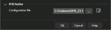
Step 5: Select the ellipsis for Configuration File to select a configuration file.
Step 6: Browse to the location of the default configuration file: C:\Cadence\SPB_[version]\tools\capture\allegro.cfg. Select the file and click Open.
Step 7: Click OK to save the settings and close the window.
Note: Other options are available for changing an existing PCB layout, including:
- Allow Etch Removal: Allow etch ripup if a component is replaced.
- Create User Defined Properties: Add user-defined properties to the component objects in the PCB.
- Place Changed Component: Choose whether to place changed components in the canvas.
- Ignore Fixed Property: Select No to not remove any fixed components.
- Constraints: Choose whether to sync all constraints or changed constraints only.
- Show Difference Report: Choose whether to show a difference report when the layout is modified.
Create a New PCB Layout From a Schematic
Step 8: With the design file selected in the Project Manager, select PCB > New Layout from the menu.
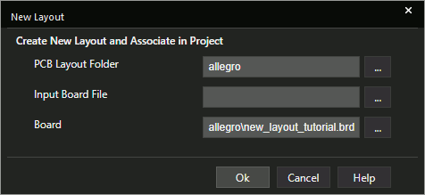
Step 9: The New Layout window opens with the PCB Layout Folder and board name already defined. Click OK to generate the board.
Note: Here you can change the folder name/path to which board data will be saved and the name of the board. If generating a board from a template, specify the template name in the Input Board File field. Otherwise, leave the field blank.
Step 10: If multiple licenses for OrCAD X Presto are available, select the appropriate license in the Cadence Product Choices window and click OK.
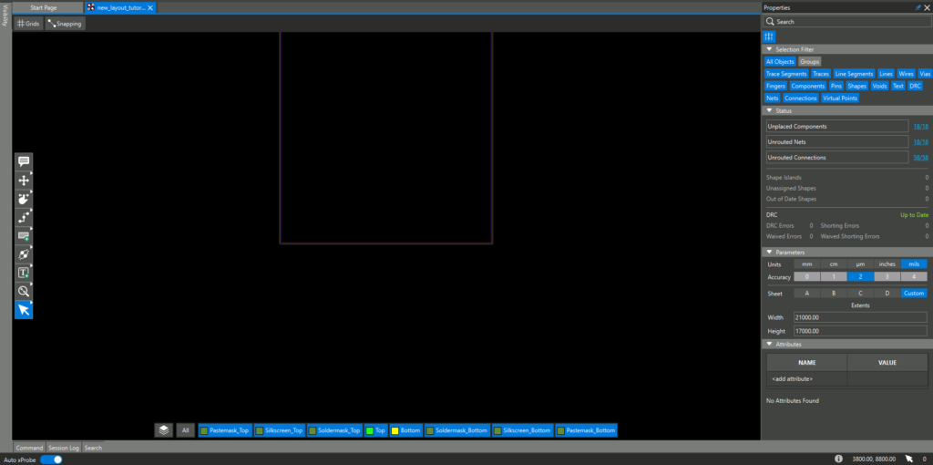
Step 11: OrCAD X Presto opens to the default blank board layout. View the canvas.
Note: If the board file does not open, select File > Open from the menu. Browse to the working directory and the generated .brd file. Select the file and click Open.
The board geometry can be adjusted depending on the project requirements. To learn how to edit board geometry, view our how-to here.
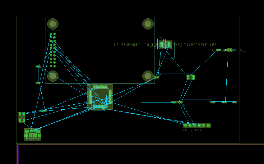
Step 12: Select ECO > Quickplace Components from the menu to place the components along the longest edge of the board. Each component is shown with the footprint assigned in the schematic.
Step 13: Select File > Save from the menu to save the PCB layout.
Wrap Up & Next Steps
Quickly create a new PCB from a schematic with bi-directional communication between OrCAD Capture and OrCAD X Presto to accurately communicate design intent. Test out this feature and more with a free trial of OrCAD. Want to learn more about Capture? Get access to free how-tos, courses, and walk-throughs at EMA Academy.
