Modern electronics could not exist without semiconductors and digital electronics but as electronics become faster and more complex, it’s essential to model realistic behavior to ensure design accuracy. In order to accurately simulate digital circuits that include latches, flipflops, gates, and other digital components, a digital source is required. A digital pulse SPICE model can be used in circuit simulation tools to generate a digital pulse waveform alternating between two voltage levels with defined characteristics like amplitude, period, rise time, and pulse width. PSpice allows you to quickly create a custom digital pulse SPICE model for accurate simulation of digital designs with a wizard-based approach.
This quick how-to will provide step-by-step instructions on how to create a digital pulse SPICE model with the Modeling Application in PSpice Designer.
To follow along, download the provided files above the table of contents.
How-To Video
 Open in New Window
Create a Digital Pulse SPICE Model
Step 1: Open the provided design in PSpice 23.1.
Note: A wizard-based approach to digital models is new in version 23.1. See other new features here.
Step 2: Select Place > PSpice Part > Modeling Application from the menu.
Step 3: In the Modeling Application, expand Sources.
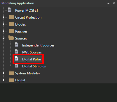
Step 4: Select Digital Pulse.
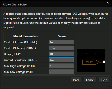
Step 5: The PSpice Digital Pulse options window opens. Enter the following model parameters:
- Clock OFF Time: 1u
- Clock ON Time: 0.5u
- Delay: 10u
- Output Resistance: 1m
Note: The logic device being modeled has negligible output resistance and requires negligible input current. Learn how to identify these parameters from device datasheets to create a realistic representation of digital pulses here.
Step 6: Click Place.
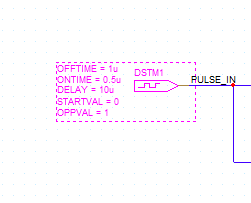
Step 7: Click to place the digital pulse source in the schematic.
Step 8: Select the Voltage/Level Marker button from the toolbar.
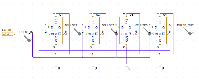
Step 9: Click to place probes on the PULSE_IN, PULSE1-PULSE3, and PULSE_OUT nets. Right-click and select End Mode when finished.
Running the Simulation
Step 10: Select PSpice > Run from the menu.
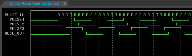
Step 11: View the simulation results. The cascading behavior of each flip-flop output is shown as a digital pulse.
Modify a Digital Pulse SPICE Model
Step 12: Back in the schematic, right-click the pulse input and select More > Edit PSpice Component.
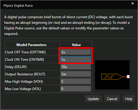
Step 13: Set the Clock OFF Time to 2u and the Clock ON Time to 1u to lengthen the clock period.
Step 14: Click Update.
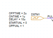
Note: This change is shown in the visible parameters to the left of the stimulus object. To quickly change these parameters, double-click a parameter and enter the desired value.
Step 15: Select PSpice > Run from the menu.
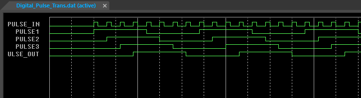
Step 16: View the results. The frequency of each pulse has been reduced.
Wrap Up & Next Steps
Quickly create the required digital pulse SPICE model for your design and simulate accurate digital circuit behavior with the PSpice Modeling Application. Upgrade to the latest 23.1 release or test out this feature and more with a free trial of OrCAD.
