To accurately communicate PCB design intent for fabrication and manufacturing, specific layers must be included in artwork files. Quickly configure artwork films in OrCAD X Presto with the easy-to-use interface during manufacturing export.
This quick how-to will provide step-by-step instructions on how to configure artwork films in OrCAD X Presto.
To follow along, download the provided files above the table of contents.
How-To Video
 Open in New Window
Configure Artwork Settings in OrCAD X Presto
Step 1: With the design open in OrCAD X Presto, select Manufacturing > Export to Manufacturing from the menu.
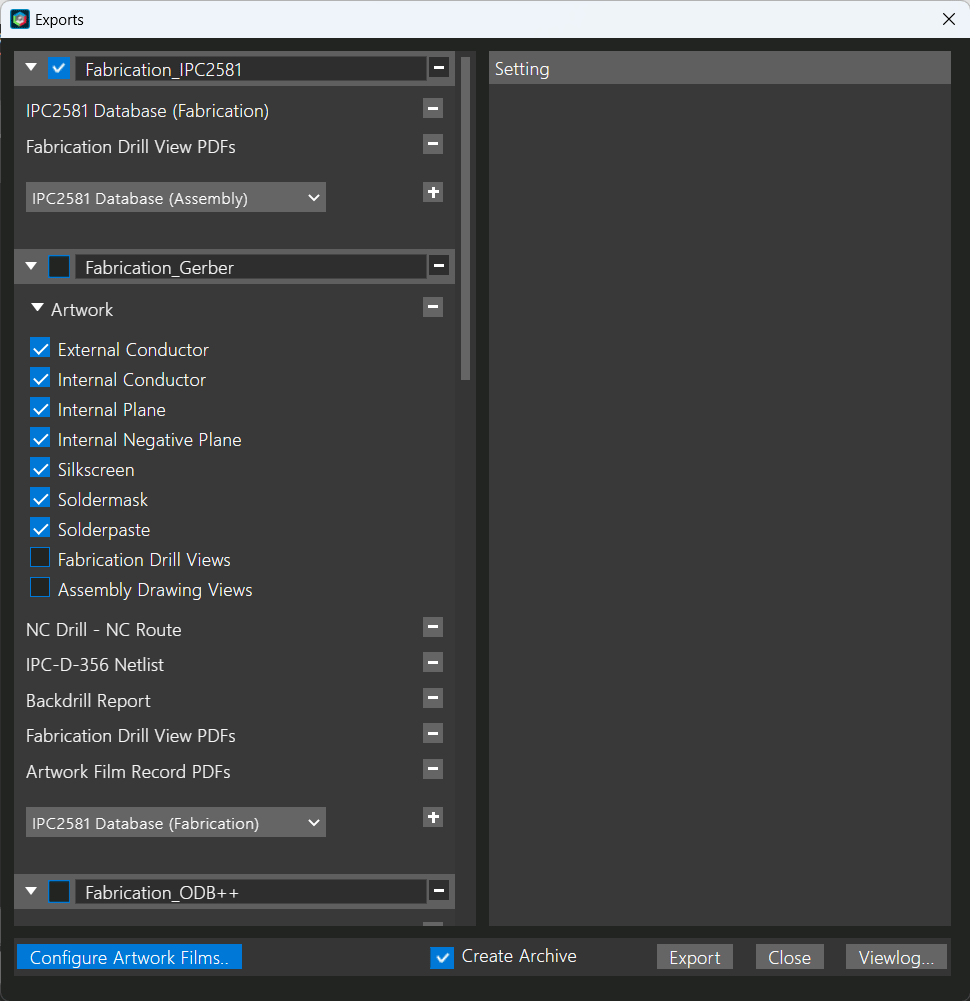
Step 2: Select Configure Artwork Films.
Step 3: View the default settings. Here you can configure default artwork settings.
Note: These settings can be configured for each individual artwork film by selecting the artwork film.
Step 4: View the default artwork films. The default films include:
- External Conductor
- Internal Conductor
- Internal Plane
- Internal Negative Plane
- Silkscreen
- Soldermask
- Solderpaste
- Fabrication Drill Views
- Assembly Drawing Views
Note: Silkscreen, Soldermask, Solderpaste, and Assembly Drawing Views contain subcategories for top (TP) and bottom (BT) layers.
Configure Artwork Films in OrCAD X Presto
Step 5: Scroll to the bottom of the configure artwork film window. Here you can see two blank boxes:
- The light gray box will add a subcategory to the Assembly Drawing Views.
- The dark gray box will add a new artwork film.
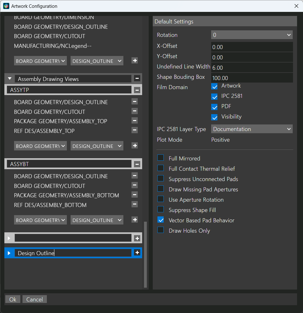
Step 6: In the dark gray box, enter Design Outline and press + to add the artwork film.
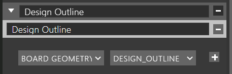
Step 7: A light gray box has appeared under the Design Outline artwork film. This will add a subcategory to the Design Outline Artwork Film. Enter Design Outline in the light gray box and press + to add the subcategory.
Step 8: In the subcategory, class and subclass definitions are now available. Select the drop-down arrow for Board Geometry. Here you can view the available classes for elements in the PCB design. Select the arrow again to close the list or choose Board Geometry from the list.
Step 9: Select the drop-down list for Design_Outline. Here you can view the available Board Geometry elements in the design. Select the arrow again to close the list or choose Design_Outline.
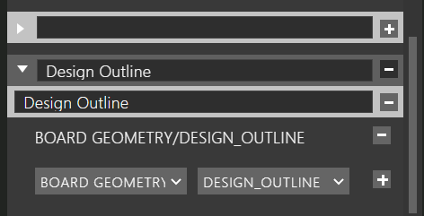
Step 10: Select + to add the design outline layer to the artwork film.
Step 11: Repeat this process as needed to modify any default artwork films or create any new artwork films.
Note: If you are adding layers to artwork films, be sure to select the + sign to add the layer.
Step 12: When finished, click OK.
Including Artwork Films in your Manufacturing Export
Step 13: Back in the Manufacturing Export window, view the Fabrication_Gerber category.
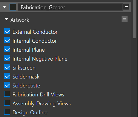
Step 14: The newly defined artwork film is now visible. Select the check box next to the Design Outline category.
Step 15: Continue with the Manufacturing Export as required.
Note: For more information on exporting a manufacturing package, view our how-to here.
Wrap Up & Next Steps
Easily configure artwork films to accurately communicate your PCB design intent for manufacturing with OrCAD X Presto. Try out this feature and more with a free trial of OrCAD X Presto and for more step-by-step instructions, courses, and walk-throughs visit EMA Academy.

