The Allegro PCB 17.2-2016 release is loaded with enhancements related to the DRILL.
We have added Pad Definition support for the Actual Drill Tool, Backdrill Tool, Square Drill, Counter Bore/Sink objects and expanded tolerance for slots. By popular demand, Backdrill sites are now fully supported with DRC clearance rules (Top 10 Reason #4).
Also new is a behavioral change to the standard Drill Hole Spacing DRC. Back in release 16.2, we provided the Drill Hole DRC to support the “Dynamic Unused Pad Suppression” application. The check only functions when the pad is removed or is smaller than the drill hole size (spotter pad). Since that time there has been heavy demand to support the Drill Hole check, whether the pad is present or not.
Enhanced Drill Hole DRC
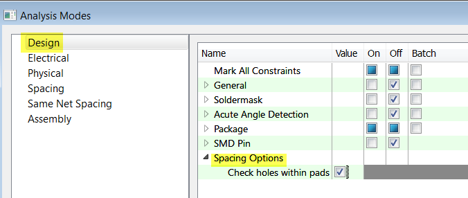
In Allegro PCB 17.2, a new Spacing Options toggle control has been added to the Analysis Modes – Design Mode menu called ‘Check holes within pads.’
- When the toggle is ON, drill-hole checks are run using the drill hole explicitly (the presence of pads associated with the drill hole is not relevant in this mode of the DRC calculation). In other words, the drill is checked whether a pad is present or not.
- When the toggle is OFF, the drill-hole checks are only relevant when the pad is suppressed or undefined exposing the bare hole. This is the default configuration and is compatible with previous releases.
Acute Angle Detection
A suite of four angle based checks are introduced as Design Level DRCs. The acute angle checks are enabled through the new Setup-> Constraints -> Modes command, then selecting the Design Modes (Acute Angle Detection) entry in the Analysis Modes form. The DRC mode may be set to On-line, Off, or Batch modes while the angle values can be set in the range of degrees.
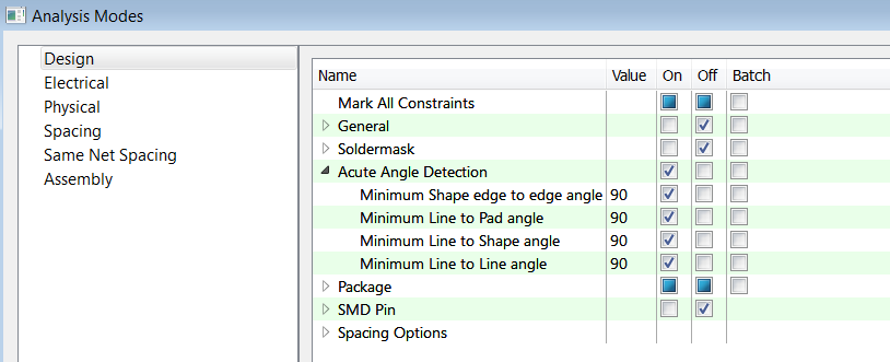
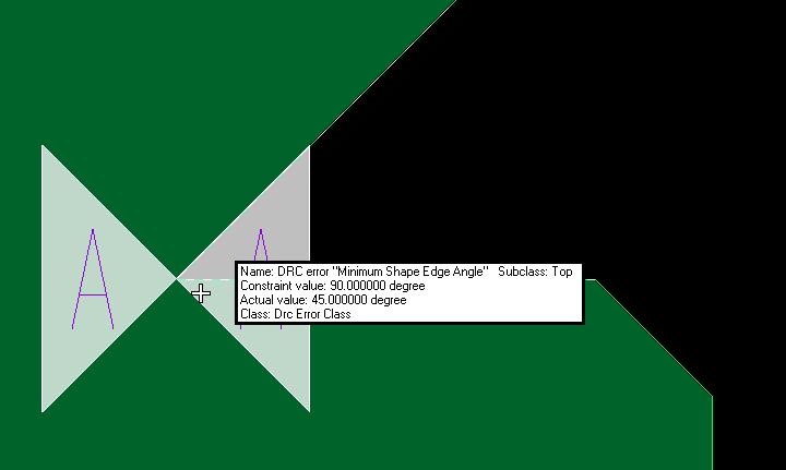
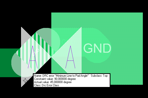
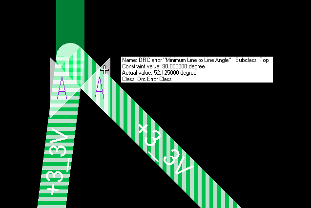
When an Acute Angle DRC is viewed, the DRC marker contains the Characters “AA” to identify the DRC as an Acute Angle violation. The Acute Angle DRC Checks performed are:
The copper shape outline has an acute angle of less the angle specified.
Cline to pad entry has created an acute angle of less than 90 degrees.
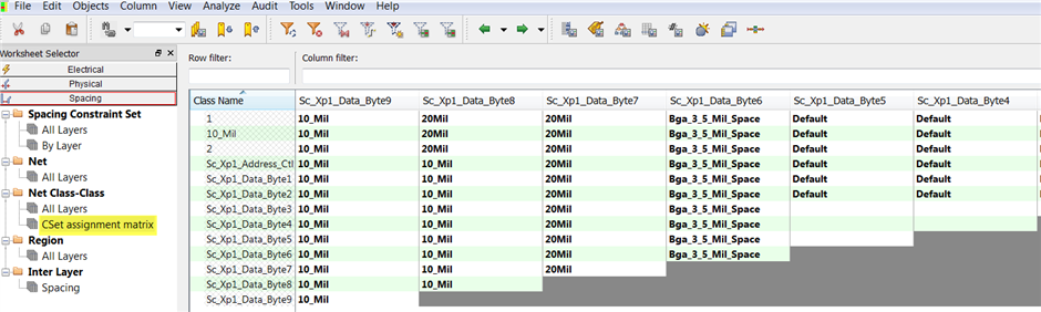
Net Class-Class Rule Assignments
Many of you have voiced your concerns to us about the way we display Net Class-Class rules in Constraint Manager. The feedback submitted to us was the current implementation is redundant and difficult to comprehend. I am happy to report our Constraint Manager team has provided an option to view the rule assignments in a two dimensional array. Navigate to the Spacing Domain – Net Class-Class worksheet where the new “Cset assignment matrix” is located.