The term electromechanical device is most often used to refer to relays, motors or generators. However, most commonly used products include both electronic and mechanical components. For example, virtually all electronic circuit boards are installed inside enclosures, many that require mounting.
Just as PCBs are designed using software, popularly referred to as electronic design automation (EDA) tools, so are plastic, metal and polymer enclosures. Traditionally, these devices have been designed in isolation, resulting in inefficient development. These practices are rapidly being replaced, as engineers and developers strive to overcome the difference between ECAD and MCAD to create more efficient and integrated design processes.
The Difference Between ECAD and MCAD
Electronic computer-aided design (ECAD) and mechanical computer-aided design (MCAD) refer to processes that employ software programs to design physical systems. Electronic circuit boards or PCBs for ECAD, and casing, enclosures or packaging, for MCAD. Although these are significant distinctions, other important differences between ECAD and MCAD exist, as listed below.
The differences above are representative of ECAD and MCAD software programs, which are not developed nor capable of effectively designing mechanical and electronic systems, respectively. Nevertheless, the need for faster, more efficient electromechanical product development is driving engineers and design teams to seek ways to bridge this divide and improve ECAD-MCAD integration.
Achieving Efficient ECAD-MCAD Integration
All ECAD programs are developed with a primary objective of enabling engineers and designers to successfully create PCB designs that satisfy electrical requirements and are buildable. Similarly, MCAD tools are developed to facilitate structure design and testing. ECAD-MCAD integration requires bridging this often-inherent divide in design tool intent. Although challenging, this goal is achievable by following guidelines, as described below.
Guidelines for ECAD-MCAD Integration Optimization
⫘ Source electronic components with accurate 3D CAD models
The quality and efficiency of ECAD-MCAD integration and your entire PCB design and development process hinges on the availability and accuracy of component CAD models. For many parts, 3D models may need to be created. Therefore, it is important to source components from a resource that includes this essential service.
⫘ Use industry standard 3D formats
There are a number of 3D MCAD file formats available. These include application specific formats; such as *.dwg (AutoCAD), *.sldprt and *.sldasm (SOLIDWORKS). There are also tool-agnostic industry standards. The *.STEP format is the most common and can be imported and exported by the leading ECAD programs.
⫘ Use a 3D product design software program
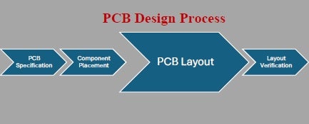
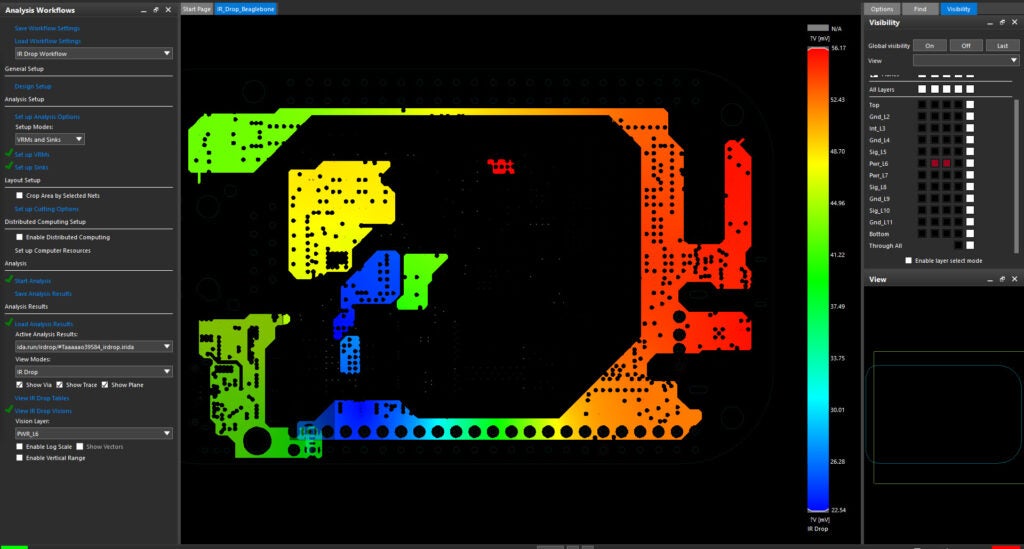
ECAD programs typically use 2D file formats for PCB design, which is sufficient for PCB schematic capture. However, to facilitate efficient ECAD-MCAD integration, 3D design capabilities for DRC checking, EM analysis and other PCB layout and verification tasks are best.
⫘ Employ software tools capable of bidirectional ECAD-MCAD translation
The best solution for achieving an optimized circuit board and mechanical system design is to employ a software integration solution that includes seamless bidirectional ECAD-MCAD translation.
The items listed above provide you with a path to successfully overcome the difference between ECAD and MCAD and develop an efficient electronic product development process. However, Incorporating these guidelines can be challenging. The best option is to partner with an industry expert experienced in providing integration software tools and support to help engineers improve their design and development.
EMA Design Automation is a leading provider of the resources that engineers rely on to accelerate innovation. We provide solutions that include PCB design and analysis packages, custom integration software, engineering expertise, and a comprehensive academy of learning and training materials, which enable you to create more efficiently. For more information on how to bridge the difference between ECAD and MCAD and how we can help you or your team innovate faster, contact us.