With the ever-increasing utilization of electronics to design more functional and capable products ranging from commercial to industrial applications, the need for a more comprehensive approach to engineering is becoming the standard. Consequently, knowing and implementing the best systems engineering tools and methods are essential for executing the efficient workflows necessary for collaborative processes, such as ECAD-MCAD development.
Systems Engineering Tools and Methods for PCB Design
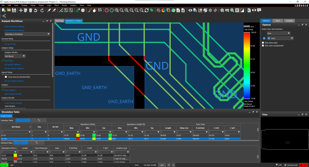
Generally, systems engineering can be thought of as applying engineering principles and methods to design and develop complex systems. For PCB designers and electronics engineers this means adopting a comprehensive approach to electronic circuit design that includes incorporating the larger system in which the board will operate. In this context, issues that affect signal integrity, such as USB interconnectivity compliance and electromagnetic compatibility (EMC), are among the major concerns that must be successfully addressed to ensure overall system operational reliability.
For effective systems level performance and reliability, all subsystems must be designed to work in concert with each other. Achieving this objective is most readily accomplished by employing the best systems engineering tools and methods, as shown below, to ensure common PCB systems design issues are targeted and goals met.
PCB Systems Engineering Tools and Methods | ||
Systems Engineering Tool | Analysis Method | Design Goals |
Signal and Power Integrity | Adequate signal propagation, matching impedance networks, maximum power transfer, adequate power distribution | |
ECAD-MCAD Integration | Ensure adequate spacing and clearances, optimize electromechanical development | |
Electro-Thermal Analysis | Acceptable heat transfer and distribution, minimize radiation-based interference, reliable structural integrity | |
Computational Fluid Dynamics (CFD) | Efficient boundary fluid flow, minimal energy losses | |
Electromechanical Co-simulation and Analysis with MATLAB Simulink | System-level electrical and electromechanical integration performance verification | |
As indicated above, the design objectives of systems engineering tools are to ensure electrical, thermal and environmental issues that can affect the operation and performance of electronics -based devices/products are prioritized during the design process. Although systems engineering analyses tools target different areas and may apply different specific mathematical and scientific methods, they share common software needs.
PCB Systems Engineering Essentials
Similar to other effective PCB design software, systems engineering tools and methods are intended to help you create the best solution that meets your board’s performance goals, while simultaneously optimizing development quality, speed and cost. How well your systems engineering analyses process contributes to these quantifying metrics depends on three essential attributes, as described below.
Essential Systems Engineering Tool Attributes |
|
|
|
Implementing Systems Engineering for Your Design
Systems analysis is typically utilized for complex PCB development, especially electromechanical designs or when boards will be implemented for automotive, aerospace, industrial or medical device systems. For success, it is important to follow guidelines for systems engineering tools and methods optimization.
Systems Engineering Tools and Methods Application Guidelines
- Make sure your tool includes functionality that targets your special system design target area or concern.
- Make sure your tool integrates easily with your EDA software.
- Make sure your tool uses accurate CAD models.
- Make sure your tool provides options for computational resource allocation and is scalable.
- Make sure your tool provides graphical results, in addition to other formats.
By following the guidelines above, arriving at the best systems analysis tool for your PCB design is achievable. Nevertheless, the process and researching and comparing available options can be a daunting task. A better alternative is probably to rely on an industry leader that excels in furnishing PCB designers and engineers with the right software, training and support to optimize their design and development workflow process.
EMA Design Automation is a leading provider of the resources that engineers rely on to accelerate innovation. We provide solutions that include PCB design and analysis packages, custom integration software, engineering expertise, and a comprehensive academy of learning and training materials, which enable you to create more efficiently. For more information on systems engineering tools and methods and how we can help you or your team innovate faster, contact us.


