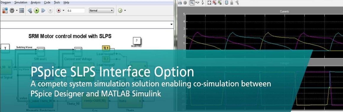
When designing a complete system, you have to simulate and model the entire system, understanding the effects of the electronics that are controlling and monitoring the mechanical, thermal, and hydraulic parts of your system, in addition to simulating the effects of mechanical portions on the electronic portion of your system. In today’s competitive design world, many companies are creating complicated devices and have little to no room for error or delays. With Cadence’s PSpice and MathWorks Simulink electrical engineers are now provided with a complete system-level simulation solution to PCB design and implementation.
The SLPS (Simulink PSspice) system utilizes PSpice for analog/digital mixed signal simulation and MATLAB/Simulink for behavioral-level modeling, analysis, and visualization of an integrated environment. This partnership provides a bi-directional interface addressing customer challenges in streamlining system-level design and circuit-level implementation. It is now possible to simulate and analyze the entire electrical, mechanical, and thermal-hydraulic system all in one design environment.
SLPS is a complete PCB design analysis and implementation solution. This integration enables users to improve their reliability, increase product performance, and lower costs all while accelerating the time to market.
How it works:
Co-simulation with both MATLAB and PSpice simulators is used to analyze complete systems. Design software algorithms in Simulink, and describe your hardware in PSpice. A majority of systems are implemented with digital and analog blocks. The challenge is to test and verify both blocks against the specification prior to building a prototype. The key is to detect errors in the design process as early as possible.
- Digital blocks can be described and developed in MATLAB Simulink
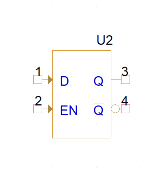
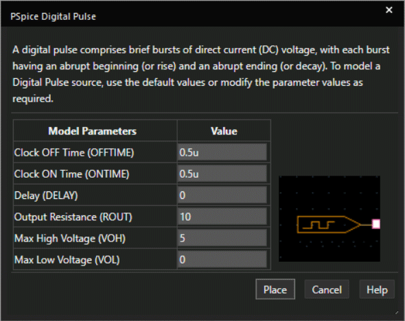
- Analog blocks can be captured and modeled in PSpice
- SLPS enables engineers to run a co-simulation for a complete system model for test and verification of digital and analog blocks.
Overview Video:
Interfaces supported by PSpice and MATLAB/Simulink integration:
There are four total interfaces supported by the PSpice and MATLAB/Simulink integration satisfying different design needs of the user. The following categories describe the benefits of each interface.
Simulink/PSpice Interface: Simulate between PSpice designer and Simulink. The Simulink/PSpice interface allows designers to simulate complete systems in a virtual prototype environment, including the simulation of ideas with ideal models or actual electrical designs without the need to prototype the entire system. This is especially ideal those in the automotive industry where co-simulations can verify how rotor speed and torque respond depending on different load scenarios and control algorithms.
PSpice Device Model Interface: Electrical engineers can now overcome design challenges by automating code generation for multi-level abstraction models written in C/C++ and SystemC with the virtual prototyping functionality of PSpice Device Model Interface (DMI). With this bi-directional flow, customers can import a Simulink model and co-simulate in Pspice. This is an ideal interface for engineers designing devices for IoT applications. In order to create working IoT devices, a unified design environment is essential for both modeling and analysis.
PSpice/MATLAB Visualization Interface: View PSpice simulation results in MATLAB and leverage advanced MATLAB plotting functions on PSpice simulation results. New menu options in PSpice allow you to easily export to MATLAB allowing users to boost powerful waveform analysis by viewing PSpice simulation results in MATLAB and customize waveform processing on export.
PSpice/MATLAB Functions Interface: Use the PSpice/MATLAB functions for fast mathematical computation. This is essential for performing complex mathematical computations during the waveform analysis. Use functions directly in measurement expression and behavioral modeling within PSpice and Capture/DEHDL environment.
For more information check out our PSpice – MATLAB / Simulink page. If you are going to CDNLive! Don’t miss Mathworks and Cadence present this integration together – find out more here