With the launch of the new Constraint Manager for OrCAD, the topic of differential pairs (and how to constrain them) seems to come up repeatedly. We are not surprised, since differential pairs are included in much of today’s designs.
The inclusion of differential pairs within a design introduces a wide variety of concerns engineers need to be mindful of if they want them to be reliable. Differential pairs are prone to problems if routing requirements and other guidelines are not followed, therefore it is imperative they are done correctly and design rules are always defined and adhered to.
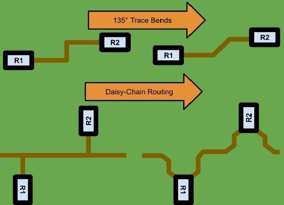
To help you as you navigate these rules and help provide some clarity on the topic, we have created an infographic: The Anatomy of a Differential Pair, which you can download here or by clicking the image above.
This infographic will provide you with some design guidelines you should keep in mind when working with differential pairs. For you to fully understand the infographic, you need to be familiar with differential pair terms and their definitions. If you are not, don’t worry, you can find a small glossary defining them below.
- Pin Pitch: The linear measurement between the pins of a component.
- Phase: Refers to the relationship of two signals to each other.
- Phase Tolerance: If you have critical nets, the same length or delay is very important for signal quality. Phase Tolerance is how much variation in either length or delay you can tolerate before you experience signal quality issues.
- Gap: The space between the two traces (Air Gap).
- Primary Gap: The air gap in the differential pair where standard values are used.
- Neck Width and Neck Gap: Similar to Primary Gap. Used in the tight pin pitch areas of components when the gap needs to “neck” down to fit the diff pair through.
- Min Line spacing: The minimum allowable air gap for the differential pair, taking into account the Neck Gap for tight pin pitches.
- Primary Width: The width of the etch/trace used in the differential pair to correspond with the stack up to get the impedance needed.
- Separation Gap Tolerance: The amount of deviation allowed within the Gap per the spec.
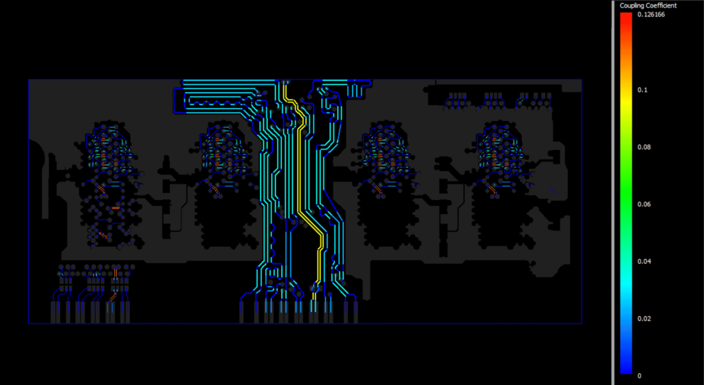
- Coupling: The desirable or undesirable transfer of energy from one medium to another.
- Max Uncoupled Length: Specifies the value for the maximum permissible uncoupled length between positive and negative nets within the differential pair.
If you have specific questions regarding actual differential pair values, be sure to contact your component manufacturer. Manufacturers are usually more than willing to provide information on the components they offer. Once you have an understanding of the guidelines listed and you have spoken with your manufacturer, the next logical step is to ensure whatever rules you have in place are being followed throughout the design process. Adopting a constraint-driven design flow can help to ensure your design specs are adhered to throughout all design stages. A constraint-driven design flow is a design with all design rules loaded directly into the software—eliminating the need for an error-prone, manual checking process. This enables the software to perform all the online rule checking to ensure the design is correct by construction throughout the design process.
Differential pairs are just one aspect of your design and how they are tackled can affect its success (or failure). With the number of constraints and managed nets continuing to increase, keeping track of rules (like the ones listed in this infographic) becomes an arduous task. Implementing a constraint-driven workflow can help mitigate potential issues that may arise—preventing bad designs from going to production.