Modeling designs helps engineers verify whether their circuit will function as intended. Modeling programs simulate circuit behavior under different conditions and in accordance with the design requirements, allowing engineers to better plan and build circuits.
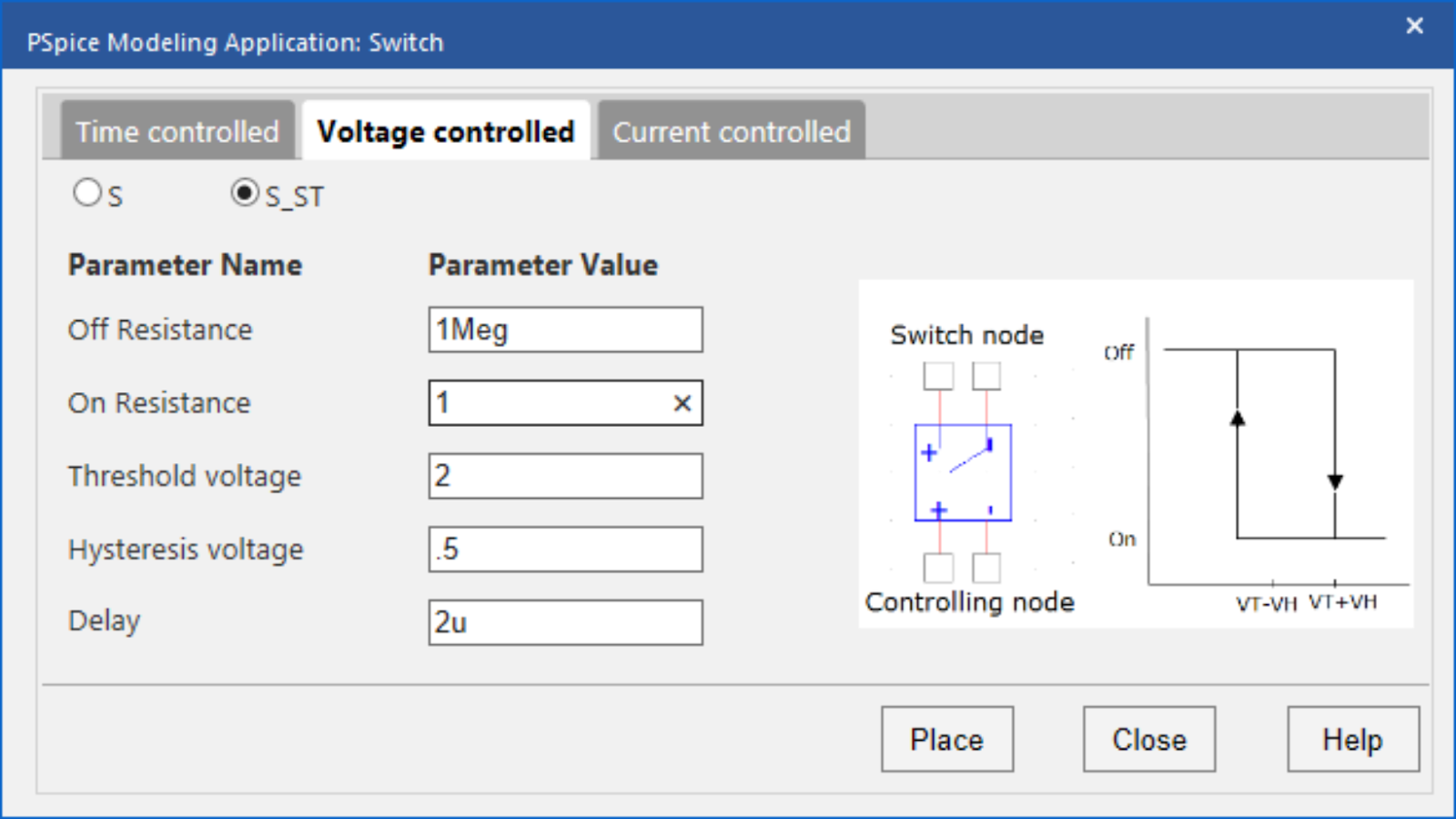
Typically, to model components, generic models are used, which produce inaccurate and unrealistic simulations based on ideal conditions. This can cause functionality issues to go undetected until far later in the design process. To confidently simulate a component, create a switch SPICE model using specifications from a manufacturer’s datasheet.
What is a Switch?
A switch is a device that can disconnect or connect the current flow in an electrical circuit, by either interrupting the electric current or diverting it from one conductor to another. Every electrical and electronics application uses at least one switch to perform ON and OFF operation of the device.
When the switch changes states and returns to the initial state (example: ON-OFF-ON), the initial and returning states will not be exactly the same. The difference between these points is hysteresis. Hysteresis is often incorporated to ensure stable switching and prevent oscillation around the defined point.
What is Needed to Model a Switch?
To create the required switch SPICE model for simulation, there are three items that must be defined:
- Switch Control
- What is the controlling factor for the switch: time, voltage, or current?
- Type of Switch Model
- Does hysteresis need to be modeled or is a simple switch sufficient?
- Switching Parameters
- What are the required parameters for the switch: on/off values, resistance, delay, etc?
This information must be incorporated into the SPICE simulation model which can be achieved by manually creating or editing a text file. Keep in mind if the model created does not produce the intended outcome or if a part is changed, values will need to be edited manually. This manual process to produce the desired model is time consuming and increases the likelihood of errors; however, the PSpice Modeling App provides a fast, easily configurable, and fully integrated method to create a switch SPICE model for simulation.
Creating a Switch SPICE Model with PSpice
The switch modeling application quickly create a switch SPICE model in various configurations with a wizard-based approach. The necessary specifications are pre-defined based on the type of switch and users can easily input the parameters required for all switches:
- Type:
Select either time-controlled, voltage-controlled, or current-controlled.
- Switch Configuration:
Select either a simple switch configuration or a switch with hysteresis. For voltage-controlled and current-controlled switches, select from simple (S/W) or with hysteresis (S_ST/W_ST). Only simple switches are created for time-controlled switches.
Based on the switch configuration, the modeling application will define the required parameters. Many of these parameters can be found on the manufacturer’s datasheet. Every switch requires the following:
- OFF Resistance:
Define the ohmic resistance between terminals when the switch is off. This is required for all types of switches.
- ON Resistance:
Define the ohmic resistance between terminals when the switch is on. This is required for all types of switches.
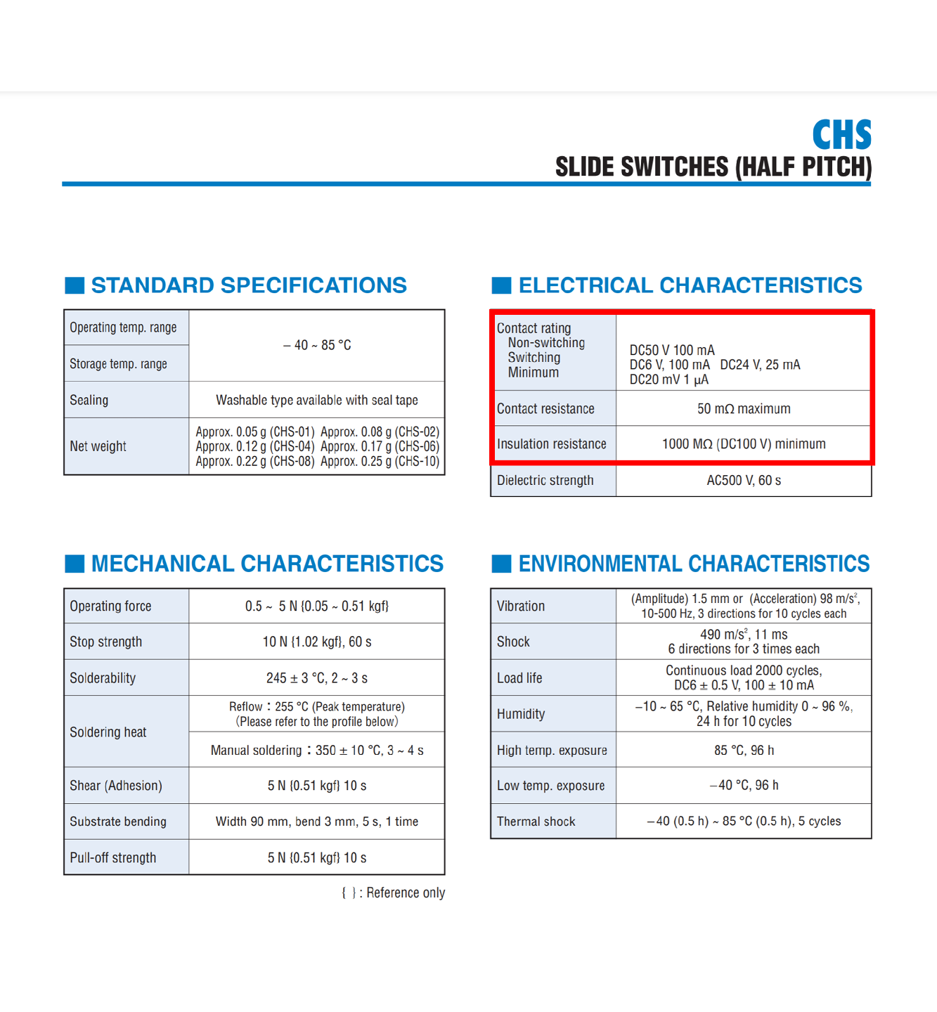
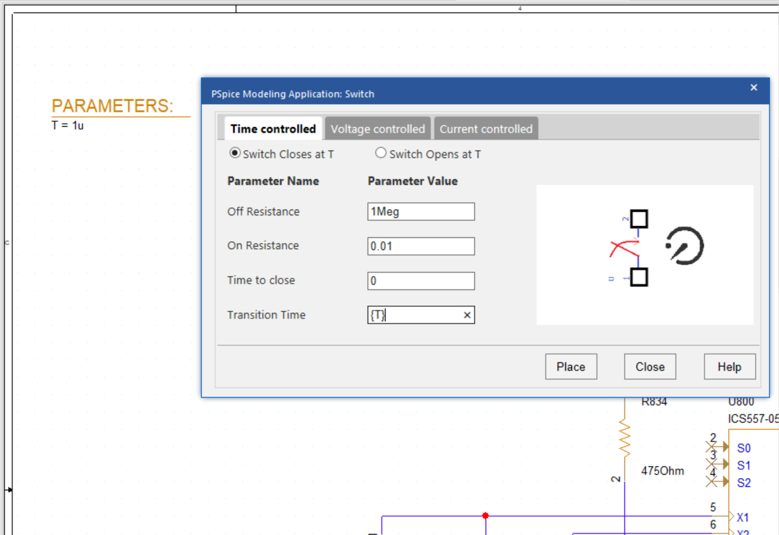
Time-Controlled Simple Switches
Time-controlled switches have two options available:
- Switch closes at a designated time
- Switch opens at a designated time.
For these switches, the following additional parameters need to be defined:
- Switch Configuration:
Select either a switch that opens or closes at a designated time.
- Time to Open or Close:
Specify the time the switch begins to open or close.
- Transition Time:
Specify how long it takes to open or close the switch. Realistically, the time it takes for the switch to change states will not be 0.
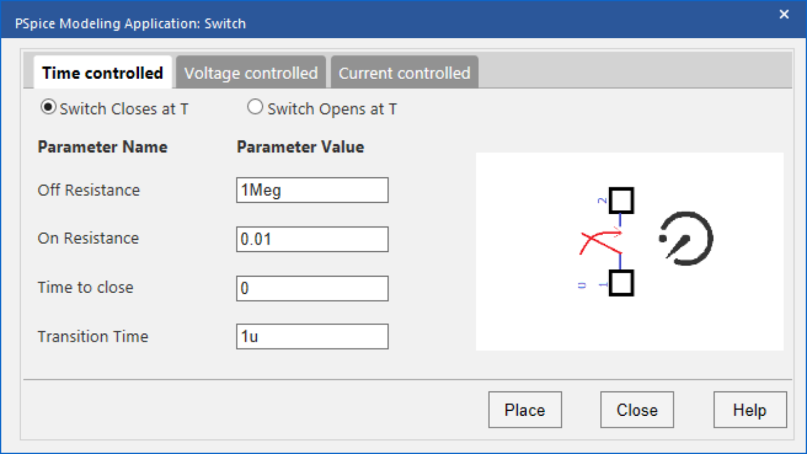
Voltage or Current-Controlled Simple Switches
For simple voltage-controlled or current controlled switches, these additional parameters must be defined:
- Off Voltage/Current (VOFF/IOFF)
Specify the threshold control voltage or current for opening the switch.
- On Voltage/Current (VON/ION)
Specify the threshold control voltage or current for closing the switch.
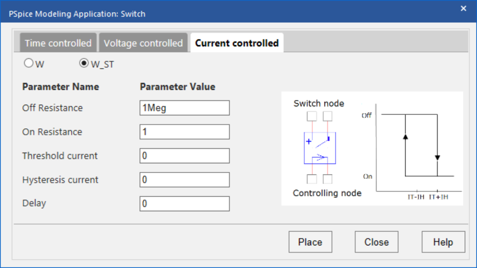
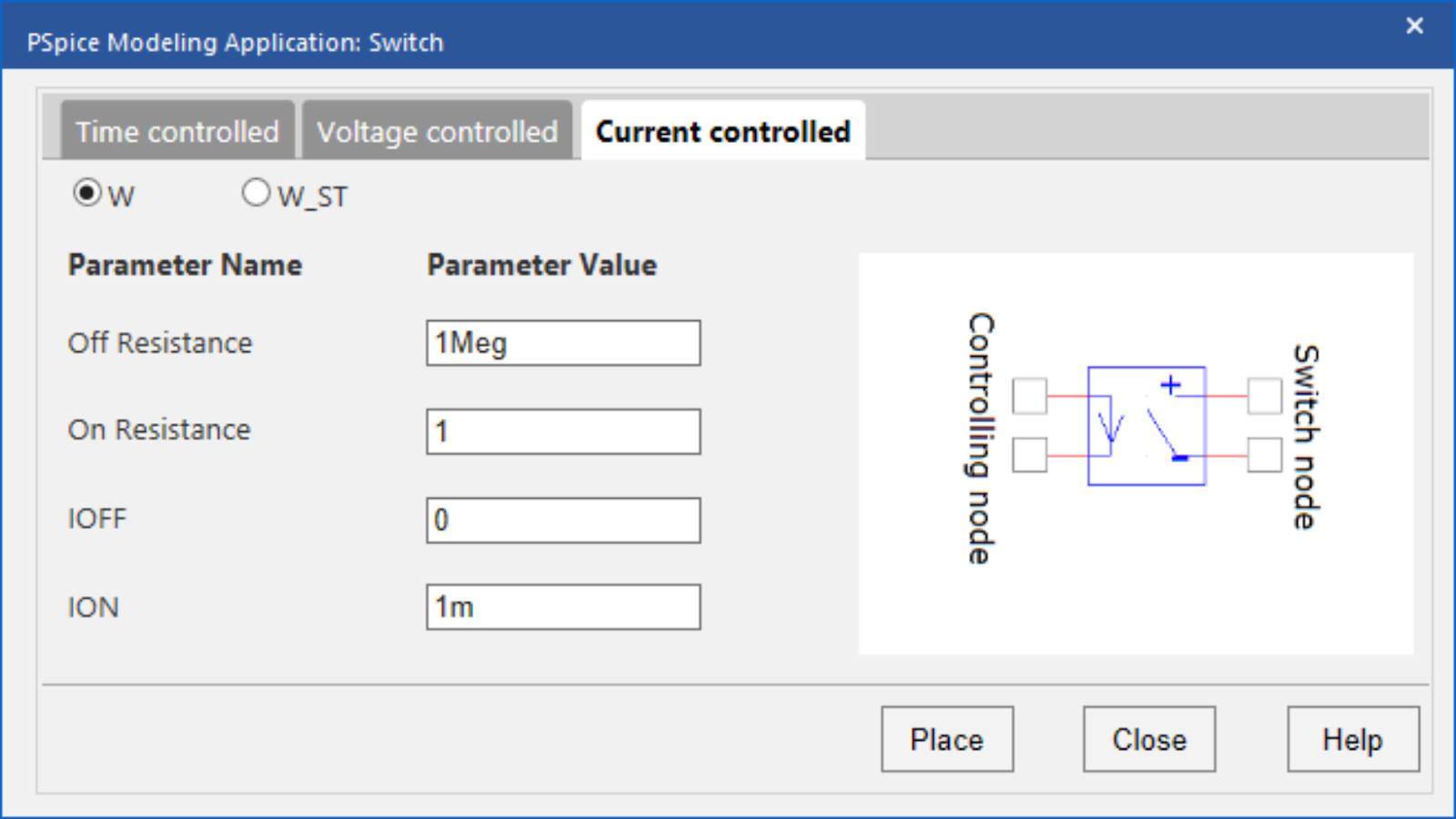
Switches with Hysteresis
For voltage-controlled switches and current-controlled switches, the option is available to include hysteresis. These types of switches require the following parameters:
- Threshold Voltage/Current:
Specify the threshold control voltage.
- Hysteresis Voltage/Current:
Specify the hysteresis voltage. The switch will turn from off to on when the voltage/current applied equals the threshold value plus the hysteresis value. The switch will turn from on to off when the voltage/current applied equals the threshold value minus the hysteresis value.
- Delay:
Specify the time delay for the switching to occur. All switch models have built-in checks for a dynamic range of parameters. If there are any violations or errors in the specified values, then these are displayed in the user interface.
The ease-of-use is amplified with the incorporation of equations into the user-defined parameters. By specifying an equation, rather than a value, the switch model can be altered without activating the modeling application. Values can be defined and edited directly on the schematic for efficient modeling and simulation.
Using the inputted information above, the PSpice Modeling App generates a schematic symbol and automatically associates the newly created switch SPICE model without leaving the OrCAD Capture environment. The PSpice Modeling App also automatically manages the simulation profile configuration, eliminating any library set up for simulation. To try this yourself, be sure to download the Free Trial of OrCAD and check back for additional SPICE model how-tos. To get the step-by-step instructions for creating and using switch models in your PSpice simulations, view our how-to.