Differential pairs are becoming increasingly prevalent in today’s designs and incorrect implementation will have detrimental effects on signal integrity. Creating an effective differential pair can be difficult, as they must adhere to specific rules. In this post, we’ll provide five tips for defining and routing these crucial differential pairs in your PCB designs.
Why are Differential Pairs Important?
Before we begin with tips, let’s discuss the basics of differential pairs. Differential signaling (termed a “differential pair”) uses two complementary signals to transmit one data signal. Differential pairs use the difference between the inverted and non-inverted signals to reduce noise. This becomes an essential tool to manage noise and improve signal quality in today’s complex, high-speed designs.

Five Tips for Creating an Effective Differential Pair
1. Route the Diff Pairs Together
The two traces of the pair must be clearly identified as a diff pair for the layout team. This ensures traces are routed in parallel across the entire length of the signal.
2. Ensure Traces are of Equal Length
The traces must be equal in length to ensure there are no timing differences between the signals of the pair. If the traces are not identical, EMI problems may arise.
3. Couple Signals to Cancel Noise
Keep the spacing between the pair small enough to couple the signals, but not small enough to interfere with manufacturing capabilities. It should also be noted to keep the differential pair lines as far as possible from other traces. (Approximately 3x the trace width.) This will help avoid additional noise and EMI within your designs while adhering to differential impedance requirements.
4. Keep Consistent Width
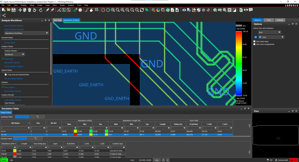
While line widths will vary on each layer of the board due to impedance requirements, it is important to keep the line width consistent between signals, even when necking down. This will ensure your impedance goals are met.
5. Utilize Differential Pair Custom Workflows
Take advantage of a defined workflow to manage the complex rules associated with differential pairs. This will create consistency throughout your design and within your team throughout implementation and layout.
Managing the multitude of rules that come with the implementation of differential pairs can be cumbersome; however, the Differential Pair Custom Workflow by EMA simplifies the process. Once installed, this free, pre-defined template walks you through the steps required to complete differential pair definition, rule setup, routing, delay tuning, and phase tuning to create successful differential pairs in your OrCAD PCB designs.


