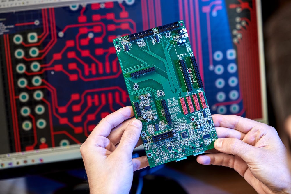
For engineers and designers creating the next generation of devices, there’s an ever-increasing emphasis on electronic circuit design analysis techniques. A comprehensive circuit analysis can differentiate between a successful new product launch and a costly redesign. The idea of “shift left” encapsulates this approach: aiming to identify and address design issues earlier in the development process. Read on as we delve into the cutting-edge techniques and tools available for circuit analysis, emphasizing the importance of proactive design evaluation.
|
ELECTRONIC CIRCUIT ANALYSIS TECHNIQUES AND TOOLS |
||
|
Technique/Tool |
Category |
Description |
|
Shift Left Design |
Design Approach |
Emphasizes early validation and testing in the design cycle. |
|
Upfront Analysis |
Proactive Techniques |
Identifies and mitigates potential issues during the design phase. |
|
In-Design Analysis |
Continuous assessment as the design progresses. |
|
|
What-If Analysis |
Simulation Selection |
Allows exploration of various design possibilities in the early stages. |
|
Sign-Off Simulations |
Rigorous simulations to ensure the design meets specifications before final sign-off. |
|
|
SPICE |
Circuit Analysis Tools |
Offers advanced circuit simulation capabilities, especially for mixed-signal designs. |
|
Generative Technologies |
Automate design processes, allowing for rapid design iterations and optimization. |
|
|
Mean Time Between Failure (MTBF) |
Specialized Analysis |
Evaluates a design’s expected reliability, especially crucial for military, aerospace, and automotive sectors. |
|
Design Software |
Includes simulation functionalities, enabling schematic designs and behavior simulations. |
|
|
FPGAs |
Emulates digital circuit behaviors to test designs in real-world conditions. |
|
|
Multimeters |
Physical Tools |
Measures circuit voltage, current, and resistance. |
|
Oscilloscopes |
Visualizes how voltage or current varies over time. |
|
|
Logic Analyzers |
Examines multiple digital signals simultaneously, detailing their timing and relationships. |
|
|
Spectrum Analyzers |
Provides insights into the magnitude of various frequency components in RF circuits. |
|
|
Laplace Transform |
Other Techniques |
Simplifies transient responses and steady-state behaviors by converting time-domain circuits to frequency domain. |
|
Phasor Analysis |
Eases AC circuit analysis by converting sinusoidal signals into rotating vectors. |
|
|
Fourier Analysis |
Reveals frequency components by decomposing complex signals. |
|
Shift Left Design: The Proactive Approach
“Shift left” is a fundamental change in approaching electronic circuit design. Traditionally, validation and testing would be performed after the design phase. But with the shift left concept, this validation process moves “left” or earlier in the design cycle. This proactive approach means:
- Upfront Analysis: By integrating circuit analysis during the design phase, potential issues can be identified and mitigated before they become significant problems.
- In-Design Analysis: As the design progresses, continuous assessment ensures that modifications align with the initial design goals, maintaining accuracy and efficiency.
Choosing the Right Simulation for the Right Time Frame
Depending on the design stage, different simulation levels may be more or less applicable:
- What-If Analysis: In the early stages, a “what if” simulation allows designers to explore various design possibilities and their implications.
- Sign-Off Simulations: In the later stages, more comprehensive and rigorous simulations are conducted to ensure the design meets all specifications and requirements before the final sign-off.
Tools of the Trade: PSpice and Generative Technologies
There are various circuit analysis tools available to engineers. Two of the most critical ones that come into play are:
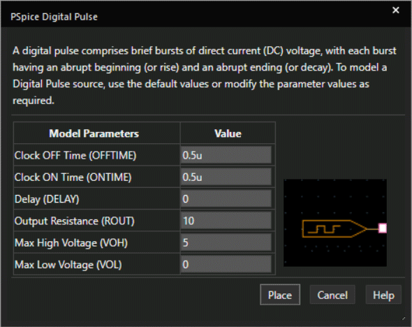
- PSpice: A widely used tool, PSpice offers advanced circuit simulation capabilities. It helps designers simulate and analyze circuit behaviors and can model complex mixed-signal designs.
- Generative Technologies encompass tools and techniques that automate design processes, utilizing algorithms to generate design variations based on set criteria. This allows for rapid design iterations and optimization.
MTBF and Automated Analysis for Specialized Sectors
MTBF (Mean Time Between Failures) is a critical metric in designs, especially for the military, aerospace, and automotive sectors. Tools like Cadence now come equipped with capabilities to automate MTBF analysis. They offer standardized and efficient ways of evaluating a design’s expected reliability, crucial for sectors where system failures can have dire consequences.
Design Software for Analyses
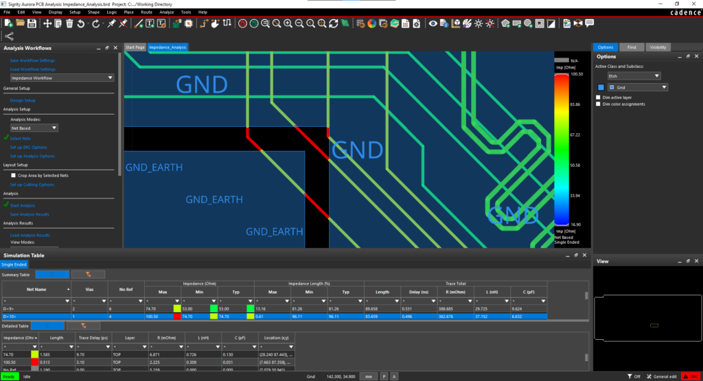
Modern electronics design often incorporates software-based simulation tools. These tools can test a design long before a physical version is built.
- EDA Software: Electronic Design Automation software, often includes simulation functionalities. This allows designers to draw their circuit schematically and then run simulations to see how it behaves.
- Field-Programmable Gate Arrays (FPGAs) can emulate how a circuit will behave for digital designs. Once the design is uploaded to the FPGA, it can be tested in real-world conditions.
Physical Circuit Analysis Tools
- Multimeters: A multimeter is a handy tool for measuring circuit voltage, current, and resistance. Ensure you have a high-quality digital multimeter with a range that suits your application.
- Oscilloscopes: For circuits that change over time (like those with alternating current), an oscilloscope visually represents how voltage or current varies. This tool is especially useful for diagnosing analog circuit issues or examining digital signals’ timing.
- Logic Analyzers: These are primarily used for digital circuits. A logic analyzer can examine multiple digital signals simultaneously and give a detailed view of their timing and relationships.
- Spectrum Analyzers: Useful for circuits involving radio frequencies, these tools provide insights into the magnitude of various frequency components.
More Electronic Circuit Analysis Techniques and Tools
Electronics engineers use a large variety of techniques to analyze and understand circuit behaviors. Here’s a compact list of key electronic circuit analysis methods:
- Phasor Analysis: Converts time-varying sinusoidal signals into rotating vectors, easing the analysis of AC circuits.
- Fourier Analysis: Decomposes complex signals into constituent sinusoids, revealing the frequency components.
- Two-Port Network Analysis: Characterizes sub-circuits using parameters like Z, Y, H, or S-parameters.
- Time-Domain Reflectometry (TDR): Detects faults in cables and transmission lines by measuring reflections from sent pulses.
- Complex Power Analysis: Evaluates AC circuits’ real, reactive, and apparent power.
- Transfer Function Analysis: This represents the ratio of system output to input in the frequency domain.
- Bode Plots: Graphically represent a system’s frequency response, showing magnitude and phase shift.
- Sensitivity Analysis: Assesses the impact of changes in component values on circuit performance.
- Monte Carlo Analysis: Uses statistical techniques to predict circuit behavior based on variability in component values
In the ever-evolving landscape of circuit design and analysis, it’s paramount to have the best tools and expertise by your side. To meet this need, you should look to an industry leader with experience providing the electronic circuit analysis techniques and software solutions for today’s and tomorrow’s PCB design challenges.
EMA Design Automation is a leading provider of the resources that engineers rely on to accelerate innovation. We provide solutions that include PCB design and analysis packages, custom integration software, and engineering expertise, which enable you to create more efficiently. For more information on electronic circuit analysis techniques and how we can help you or your team innovate faster, contact us.


