The use of bendable circuit boards continues to proliferate. Thanks in part to their use in common consumer products, like mobile phones. Flex, flexible circuits, and rigid flex are common buzz words that continue to be relevant in today’s growing electronics industry—but how much do you really know about the differences between them and when to use each type?
The use of flex circuits has been a key player in the modern technology era. In general, flexible circuits provide a solution to a variety of electronic design constraints. As the name implies, flex circuits are implemented to help PCB engineers solve important design issues. For example, providing bendability to meet product enclosure requirements, static applications where 3-axis connectivity is necessary or when space, cost, and performance are primary concerns.
Flexible circuits provide designers with more freedom to create a design to fit a particular device rather than a device to fit the circuit board design. When talking about flex circuits it is important to note that there are several different types including single-sided, double-sided, multi-layered, and rigid-flex, all serving a slightly different purpose for the PCB design and implementation. Knowing the differences between these categories of flexible circuits and following good flex PCB design guidelines are the keys to efficient design and reliable products.
Single-layer Flex Circuits
A single-layer flex circuit, also referred to as a single-sided flex circuit, is currently the most commonly used type of flexible circuit—and the cheapest. A single-layer flex circuit, as shown below, consists of one conductive layer bonded between two insulating layers or uncovered on one side with cover layers applied to improve the lifespan of the product.

This type of circuit has a very thin construction and is most effective in applications where constant motion is expected.
When to use single-layer flex circuits:
- Dynamic flexing applications
- Applications with unusual folding and forming
- Budget constraints require cheaper circuits
- You have space and thickness limitations
Double-sided Flex Circuits
Double-sided flex circuits are commonly required when circuit density and layout cannot be routed on a single layer. These circuits are comprised of two conductive layers, an insulating layer sandwiched in between, and layers connected by plated through-hole methods, as shown below.

Double-sided flex circuits are the second most popular flexible circuit used today. A major benefit of double-sided flex over single-layer flex is the ability to assemble components on both sides of the board.
When to use double-sided flex circuits:
- Applications requiring high-density interconnection of circuits
- Ground and power plane applications
- When shielding applications is important
Multi-layer Flex Circuits
For many of today’s compact electronics applications, multilayer circuits are essential. This includes multi-layer flex circuits. The major difference between double-sided flex and multi-layer flex is simply more layers. As shown in the image below, multi-layer flex circuits consist of three or more flexible conductive layers with flexible insulating layers in-between each one.
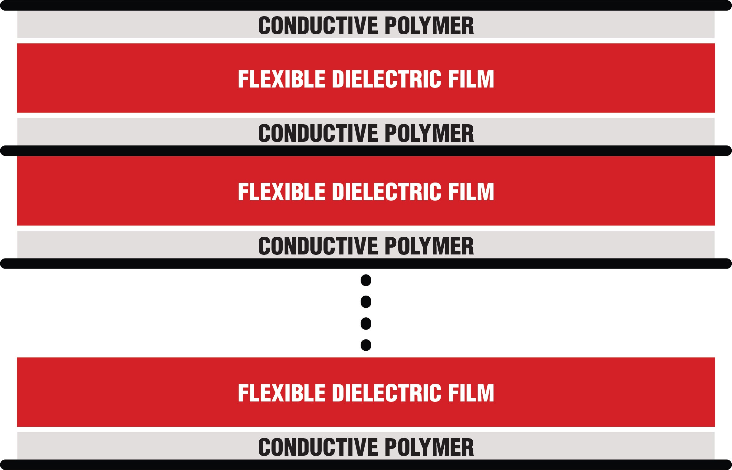
Much like the double-sided flex, multi-layer flex circuits are common in applications with high-density interconnect of circuits as well as ground and power plan applications.
When to use multi-layer flex circuits:
- Controlled impedance with shielding is important
- In dense circuit mount assembly situations
- EMI/RFI shielding is desired
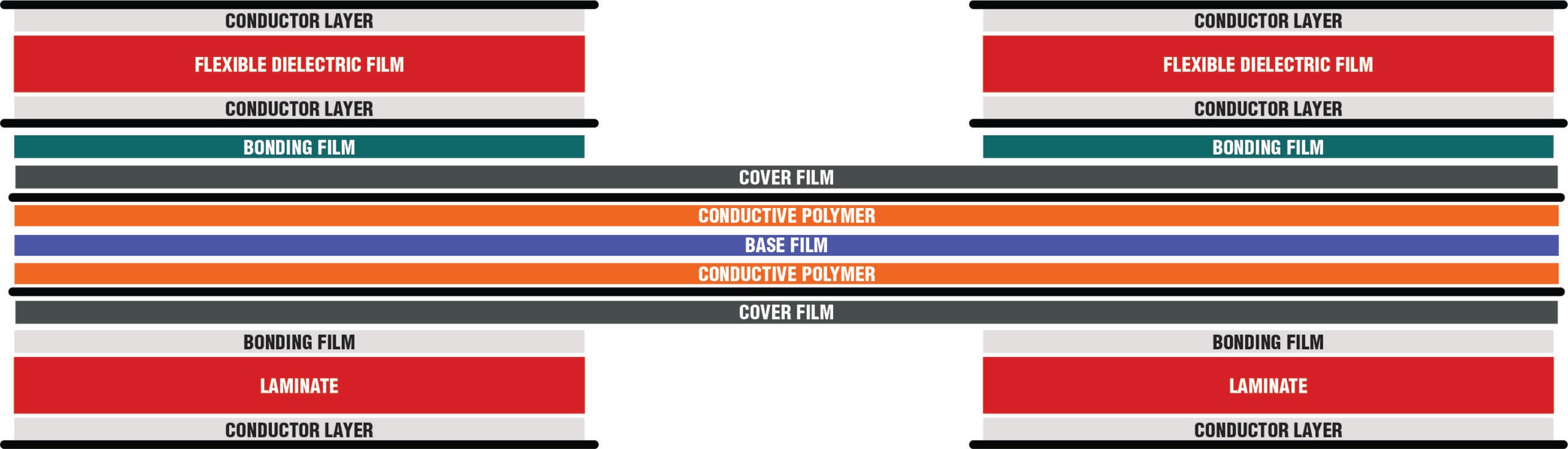
Rigid-Flex Circuits
The most recent, and most talked about, type of flexible circuit is the rigid-flex. Rigid-flex circuits consist of a hybrid configuration with two or more conductive layers and either flexible or rigid insulation depending on the application. The ability to add conductors to the rigid layers differentiates rigid-flex from multi-layer circuits with stiffeners. This type of hybrid circuit allows the designer to have the best of both worlds—implementing rigidity where extra support is needed, and flexibility in areas requiring more movement. Although rigid-flex circuits are typically reserved for higher end circuits due to their higher degree of engineering complexity and cost, they do reduce steps in the assembly process and can, in essence, shorten overall time to market. An example of rigid-flex is shown below.
When to use rigid-flex circuits:
- When application requires a maximum of three-dimensional space
- In applications where stable and flex areas are needed
- EMI/RFI shielding is desired
- Typically seen in medical, aerospace, and military applications
Implementing Flex PCB Design Guidelines
The efficiency and quality of your flex circuit design is often determined by the software used to design your PCB. An important consideration is “Does your software allow you to design the flex circuit and run all the necessary tests in a timely fashion?” Key considerations when selecting your PCB layout design software should include the following:
- Range of plating material options.
- Ability to institute industry standards for spacing and aspect ratios.
- Fixed and controlled impedance design capability.
- Stackup design flexibility.
- Fillet design capability.
- Copper selection options; such as cross-hatched.
- Coverlay design choices.
- Relief slit design.
- Material options for stiffeners.
- Ease of silkscreen marking incorporation.
For more information on good flex PCB design guidelines, see these resources.
The OrCAD X environment allows you to employ the industry’s leading software in an intuitive, easy to use platform that enables users to handle unique challenges associated with flex and rigid-flex designs. This includes new stack-up and cross section capabilities, enhanced rigid flex routing, placement, and rigid flex DRCs. For help acquiring and/or implementing these advanced capabilities into your workflow, look to the industry leader for supply software and support solutions.
EMA Design Automation is a leading provider of the resources that engineers rely on to accelerate innovation. We provide solutions that include PCB design and analysis packages, custom integration software, engineering expertise, and a comprehensive academy of learning and training materials, which enable you to create more efficiently. For more information on flex PCB design guidelines and how we can help you or your team innovate faster, contact us.