Modeling designs helps engineers verify whether their circuit will function as intended. Modeling programs simulate circuit behavior under different conditions and in accordance with the design requirements, allowing engineers to better plan and build circuits.
Every SPICE simulation needs to have a source or input signal. To analyze how the circuit will behave in real life, this input must be modeled accurately. If not modeled accurately, functionality issues can go undetected until far later in the design process, wasting time and money. To efficiently and accurately create a digital pulse SPICE model, the intended input signal must be interpreted by identifying the type and signal values for replication.
 Open in New Window
What is a Digital Pulse Source?
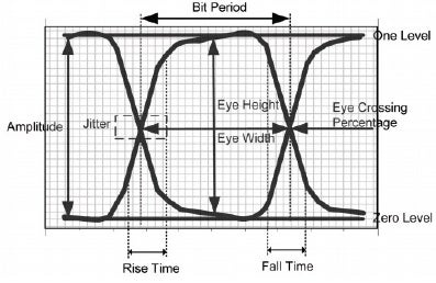
A digital pulse source SPICE model is used in circuit simulation tools like PSpice to generate a digital pulse waveform. This waveform alternates between two voltage levels, logic high and logic low, with defined characteristics like amplitude, period, rise time, and pulse width.
Digital Pulse SPICE models are useful for simulating digital circuits that include latches, flip-flops, gates, and other digital components.
What is Needed to Create a Digital Pulse Source SPICE Model?
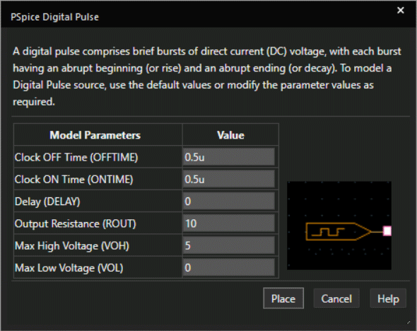
A digital pulse comprises brief bursts of direct current (DC) voltage, with each burst having an abrupt beginning (or rise) and an abrupt ending (or decay). To model a digital pulse source, there are a few items that must be defined:
Timing Parameters
- How long is the clock signal low and high?
- How long is the delay between the input and output?
Electrical Characteristics
- What is the resistance at the output pin if connected to an analog device?
- What are the high and low output voltage levels?
This information must be incorporated into the SPICE simulation model which can be achieved by manually creating or editing a text file. Keep in mind if the source signal created is not the intended outcome, values will need to be edited manually. This manual process to produce the desired source signal is time consuming and increases the likelihood of errors; however, the PSpice Modeling App provides a fast, easily configurable, and fully integrated method to create digital pulse SPICE models for simulation.
Creating a Digital Pulse SPICE Model with PSpice
The digital pulse modeling application quickly creates a digital pulse SPICE model with a wizard-based approach. The necessary source specifications are pre-defined, and users can easily input desired parameters required such as:
Clock Off Time
The time duration when the clock is low. If no unit is specified, the default unit is seconds.
Clock On Time
The time duration when the clock is high. If no unit is specified, the default unit is seconds.
Delay
The delay at the output pin in seconds.
Output Resistance (ROUT)
Specify output pin series resistance in ohms, if connected to an analog device.
Max High Voltage
Define the output high voltage (V), if connected to an analog device.
Max Low Voltage
Define the output low voltage (V), if connected to an analog device.
Using the inputted information above, the PSpice Modeling App generates a schematic symbol and automatically associates the newly created digital pulse source SPICE model without leaving the OrCAD Capture environment. The PSpice Modeling App also automatically manages the simulation profile configuration, eliminating any library set up for simulation.
To learn more, be sure to keep an eye out for additional SPICE model explanations in this series and get the step-by-step guide to create a digital pulse SPICE model here.