In the PCB design process, a digital thread refers to an interconnected digital ecosystem that links all phases of product development. A digital thread integrates different tools and data systems (CAD, CAM, ERP, PLM, etc.) to maintain continuity across departments throughout the product lifecycle. This creates a continuous flow of information between design tools, simulation environments, and manufacturing systems, allowing all stakeholders to access a single source of truth. Establishing a digital thread can have vast benefits, improving the PCB design process by:
- Ensuring data consistency
- Reducing errors due to miscommunication
- Enabling teams to leverage data and insights from all phases of PCB development
- Increasing efficiency for design and collaboration
- Providing full traceability
- Creating higher quality designs
There has been a big push to drive digitization in every aspect of business. Companies have promised their shareholders efficiencies attributed to the digital transformation of their operations, including engineering and product development. With many of today’s products being smart, connected, and multi-disciplinary in nature, they require a system comprising of hardware (electrical, mechanical, optical, etc.) and software working in harmony to accomplish the desired functionality of the product. This need for collaboration across multiple departments creates technical and organizational challenges which make it difficult to achieve a digital thread and result in a fragmented, disjointed flow commonly caused by:
Lack of Technical Integrations
Each department has different software specialized for their specific PCB design task. Bridging software differences can be complex as it requires technical integrations as well as collaboration from both departments, and without integration, manual efforts are required.
Inconsistent File and Data Formats
Different stages of the PCB design process (CAD, CAM, etc.) use diverse file and data formats, making seamless data sharing difficult. Mapping data fields and translating between file formats often leads to data loss or misinterpretation.
Isolated Data Repositories (Data Silos)
PCB design involves multiple stakeholders, including design engineers, fabricators, component suppliers, and assemblers. These entities often work with their own systems and databases, leading to isolated data repositories.
As product development evolves and becomes more complex, these technological and organizational challenges become even more apparent and can have detrimental effects on all aspects of the design process. This is especially true for the PCB design process, which relies heavily on real-time input and information from multiple stakeholders across the company.
PCB Design Challenge: Data Discontinuity
According to an Aberdeen Research Study, 44% of respondents determined the top challenge for managing their PCB design was the complexity of the data. PCB design data is highly detailed and multi-layered, involving electrical schematics, PCB layout, component libraries, simulation data and models, manufacturing instructions, bill of materials, and more.
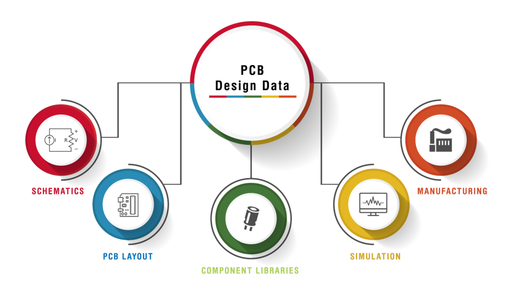
Managing and synchronizing these data types while maintaining version control and traceability is technically challenging; however, as designs become more complex and project timelines shrink, ensuring that all stakeholders involved in the design process share accurate and synchronized information becomes harder and event more essential. Part Availability and ECO Management are two prime examples of data discontinuity in PCB design flows.
Part Availability
The market for electrical components can be volatile at times -components that were available at the beginning of the PCB design process may no longer be available when the Bill of Materials (BOM) is sent to purchasing, or critical components may not be available for the duration of the product lifecycle resulting in an earlier than expected redesign Unavailable components will require trade-off decisions to keep the project on track and on budget such as:
- Swapping Parts
Best case scenario – there is a part that is an exact replacement that can be swapped into the design. This will result in minimal changes to the design and BOM while still allowing purchasing and manufacturing to continue with minimal delays.
- Stalled Production
Instead of swapping parts or redesigning your board, you may opt to wait until the part can be shipped and assembled. This will depend on the lead time in relation to the project timeline and may have detrimental effects on your product launch.
- Redesigns
If a replacement part is not available and production is delayed, a new part will need to be designed for the schematic and board. This will incur manhours for the engineers and, as a result, increase the project’s costs.
Analyzing part availability by integrating your company’s PLM and CAD databases can keep you ahead of these issues, keep purchasing and engineering synced, and help engineers make informed part decisions during the schematic design, when change is easiest.
ECO Challenges
The goal of an ECO is to provide a systematic way to manage design or process changes, reduce errors, maintain consistency, and ensure that all stakeholders are aware of and can contribute to the decision-making process before changes go into effect. If an ECO is not implemented properly, it can have repercussions in the PCB design process, including:
- Decreased Product Quality
If changes aren’t communicated and implemented correctly, products may not work as intended and experience defects, malfunctions, or safety hazards. This variation in performance and quality will create an inconsistent customer experience.
- Supply Chain Disruptions
Supply chain disruptions, such as delays and component shortages, can occur if parts are incorrectly changed or stocked, or there are mismatches between what is needed and what is available. Additionally, if suppliers were not notified of the ECO or it wasn’t communicated accurately, they may produce incorrect parts, causing misalignment in the supply chain.
- Internal Operational Disruptions
If ECOs are not well-communicated teams may be confused which specifications or processes to follow, leading to, errors, wasted time, and increased frustration.
ECOs are common in a product’s lifecycle. In order to implement changes efficiently in the production process, ECOs need to be communicated effectively to all stakeholders in the design process, from engineering to purchasing and manufacturing. Version history, change notifications, and tracking are integrated into company systems to ensure all departments are in sync.
Without integration and an interconnected digital ecosystem, team members are not able to see a cohesive data set or the underlying context to form a full picture of product development. When this happens, manual methods are required often consisting of logging into the PLM system to view and manage data then returning to the CAD environment to implement any changes and vice versa. This takes additional time and brings an increased possibility of errors. Integrating critical purchasing and product lifecycle data with engineering development, streamlines this process and improves collaboration.
Building a Connected Digital Thread for PCB Design
Enterprises have used various genres of applications to manage the product development and product realization process, which include:

- Mechanical CAD (SOLIDWORKDS, Creo, NX, Inventor etc.)
- Electrical CAD (Cadence, Mentor, Autodesk Eagle, Altium, Zuken, Kicad, etc.)
- Simulation
- PLM (Arena)
- Supply Chain Applications
- ERP (Netsuite, Microsoft Dynamics, Acumatica, Oracle, SAP, etc.)
However, the key to building a cohesive digital thread is connecting systems and data across the company to establish cross-department collaboration. This can be achieved through the following steps:
Step 1: Identify Software Needs
Each department is going to have different software needs. Identify the CAD, CAM and data management software that is going to be required across your company. Even though engineers use their native applications for IP creation, Product Lifecycle Management (PLM) applications have emerged as the enterprise application to manage the overall product definition across all domains. A PLM system like Arena can facilitate the starting point for your digital thread by providing an accessible platform and centralizing all data for stakeholders to access.
Step 2: Establish a Unified Data Model
Defining data formatting, naming conventions, and version control standards will help maintain consistency and traceability. This can be done through field mappings and leveraging CAD neutral formats to facilitate seamless and contextual data exchange.
Step 3: Integrate Software and Departments
Using a PLM as a stand-alone platform still requires manual methods for integrating other departments and data, such as engineering. To successfully achieve cross-department collaboration seamless data transfer must occur between the PLM and software used for engineering. This is typically achieved with an Application Programming Interface (API) to enable platform integration. APIs are a set of rules and protocols that allow different software applications to communicate with each other. APIs define the methods and data formats required to request and exchange information, enabling seamless interactions between separate systems.
Step 4: Enable Real-Time Synchronization
Data is continuously changing throughout the product development process. Real-time synchronization will keep all stakeholders up to date with advancements. This will enable them to leverage accurate data from other parts of the design process to make informed decisions- for example, identifying and using approved parts DURING component selection and schematic creation, not after.
The accuracy of the data you use throughout the PCB design process has a direct correlation to your product’s success, as inaccurate data leads to manufacturing delays, product redesigns, and increased costs. Achieving a digital thread that provides seamless, real-time collaboration across departments will streamline your product development process, establish traceability, and create high-quality designs faster.
OrCAD X & Arena PLM – Better Together

Traditionally, PLM applications have had a mechanical engineering bias, looking at PCB design software and management as an afterthought. This has been a big challenge for enterprises who understand the increased importance of incorporating electronics design as an integral part of their product development. Arena, an operations-centric PLM, eliminates this challenge by focusing on the complete BOM, including electrical assemblies, not just mechanical assemblies.
Connecting your electrical engineering environment and PLM can be achieved with the integration of OrCAD X and Arena PLM through the Advanced Arena Connector. The Advanced Arena Connector provides native integration for users to access Arena PLM data directly in OrCAD X which enables:
Enhancement | Description | Benefits |
Complete Component Data | Engineering can access complete component data from Arena PLM to consider the electrical requirements, real-time lifecycle, stock, pricing information, and more to make intelligent design decisions upfront. This synchronization and access to critical business-level component data directly inside OrCAD X helps engineers reduce late-stage design changes and guarantee timely part procurement. |
ü Latest information from Arena for your designs ü Make informed part decisions when designing ü Streamlines purchasing |
Closed Loop New Part Introduction (NPI) Process |
Ensure part qualification occurs upfront during the NPI process by automatically generating an Arena PLM part number and status for new parts introduced in the PCB design.
|
ü Designer can initiate actions from within the ECAD environment ü Streamlined part purchasing |
Zero Touch BOMs |
Efficiently communicate a complete, fully formatted BOM containing the information needed for part procurement and manufacturing directly from OrCAD X and trigger the next steps in the design process with a single-click upload to Arena PLM. |
ü Eliminates Manual Process ü No errors or modifications in the BOM ü Efficient File Sharing and Collaboration |
Where Used |
Easily identify the effect of part changes across various products without leaving the OrCAD X environment. The integration between Arena PLM and OrCAD X allows engineers to synchronize their approved manufacturer/vendor lists, locate and replace obsolete components, and guarantee only approved and available parts are used within their designs. |
ü Increased efficiency ü Native Integration- No need to leave your ECAD tool ü Ensures purchasable components |
Building Your Cohesive PCB Digital Thread with OrCAD X and Arena

Integrating engineering and enterprise with OrCAD X and Arena PLM will help you achieve a digital thread to ensure connectivity, traceability, and efficiency across the entire PCB design process- from conceptual design through part procurement to manufacturing, and even into the final product’s lifecycle. Learn more about the Advanced Arena Connector here.

