The OrCAD/Allegro 17.2-2016 release, the largest in the past 10 years, became available in late April 2016. Since 17.2-2016 includes a database change that usually happens with a dot zero release, many of you may be wondering when the right time to migrate to this new release is.
Included below is an overview of the Top 10 reasons to move up to the 17.2-2016 release, so you can better understand the value of each of the reasons. This is the first in a series of blogs to help you learn more about these new capabilities in the 17.2-2016 release and how you can benefit from them. Each week after this series of posts is published, we will peel the onion on each one of the Top 10 reasons.
1. Advanced flex and rigid-flex design support – significantly shorten your design cycle (Available in OrCAD and Allegro)
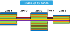
Good news for all the PCB designers who have struggled with flex and rigid-flex designs, which are increasingly used in a broad range of electronic devices and products. The 17.2-2016 release enables several new capabilities for flex and rigid-flex designs to minimize iterations with MCAD and lower the overall cost for flex and rigid-flex designs.
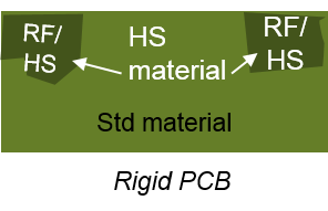
The stack-up by zones feature provides faster and easier definition of stack-ups for rigid-flex-rigid designs and improves MCAD-ECAD co-design. This new capability also enables material inlays for PCBs that have a small percentage of high-speed or RF circuitry on it. Material inlays can save up to 25% on boards with small RF/high-speed circuitry on them.
Another area of improvement includes extensive in-design rules for flex designs. This release introduces 12 new layers and 19 new finishes for flex and rigid-flex designs. More importantly, users can add new user-defined layers and surface finishes. The new in-design inter-layer checks provide the ability to check geometries between two different layers.
2. New concurrent team design capability – work together simultaneously with your team members (Available as an option in Allegro)

Have a tight design schedule? Are you working with a distributed team on the same PCB design project at the same time? With the new concurrent team design capability in the Allegro 17.2-2016 release, you can work concurrently on the same design. By connecting users to a common Allegro PCB database, multiple designers can easily work on the design at the same time, and any changes made by one team member are seen in realtime by all members. The new Allegro concurrent team design feature can shorten routing time by up to 80% for dense and complex designs.
3. New padstack editor – easy to use and supports many new pad primitives (Available in OrCAD and Allegro)
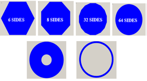
The new padstack editor will dramatically increase your productivity when creating padstack through a modern, easy-to-use GUI. A wizard-like approach makes it easy to specify all attributes needed to define and specify a padstack. The new editor provides many new primitive padstack geometries to make it easy to create complex pad / padstacks. With this release users can create padstacks with several new primitive shapes like donut shape, rounded rectangle, or chamfered rectangle, to name a few. These padstacks are not only easy to create but also help streamline the rest of the design process. The 17.2 padstack also provides support for route keepout geometry as part of its definition – objects can be controlled on each layer of the pad structure or on adjacent layers that can extend beyond the begin/end layers. Stay tuned for more.
4. The best backdrill capability in the industry just got better – easily navigate around vias marked for backdrilling (Available in Allegro)
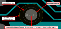
Allegro PCB Designer was the first to support backdrill capability many years ago. Based on customer feedback, we have enhanced the in-design rules for vias marked for backdrilling to make the design process even more efficient. In addition, we are providing better visuals around the vias marked for backdrilling to avoid creating problems / issues in the first place.
5. New cross-section editor – streamlines setting up of design, rules for stackup-related objects (Available in OrCAD and Allegro)
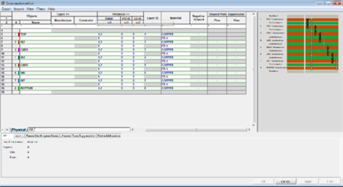
The new cross-section editor provides set up for all the features such as stack-up by zone, dynamic unused pad suppression, and embedded component design. A dynamic graphical image of the stack-up construct is shown in a dockable window as you define the stack-up characteristics. The stack-up image includes functionality to set and show reverse drill direction. Grid-editing enhancements allow you to add layer pairs or a user-defined number of layers. Miscellaneous enhancements include the increase of material character length from 19 to 250, positive/negative tolerance support for each layer, via label customization, controls to prevent editing of layers or values, and support of unnamed dielectric layers above top/below bottom. Much more to follow in a future blog post.
6. Arc aware routing with advanced contour hug saves time to route on flex designs (Available in OrCAD PCB Editor, with advanced capabilities in Allegro)
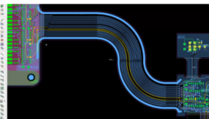
Whether you are doing flex, rigid-flex or rigid PCBs, PCB Editor’s routing has been enhanced to be arc aware. The enhanced contour hug trace addition saves users time by providing a more efficient method to add routing during Add Connect by following an existing connect line or a route keepin. It introduces a simple canvas-based two-state click use model that also enables shoving of existing connect lines. Transitions between the non-contoured and the contoured routing are smoothed for line or arc corners. You have to try this yourself to see how easy it is.
7. Tabbed routing – manage impedance and cross talk in critical signals, especially in BGA break-out regions (Available in Allegro)
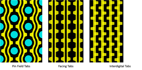
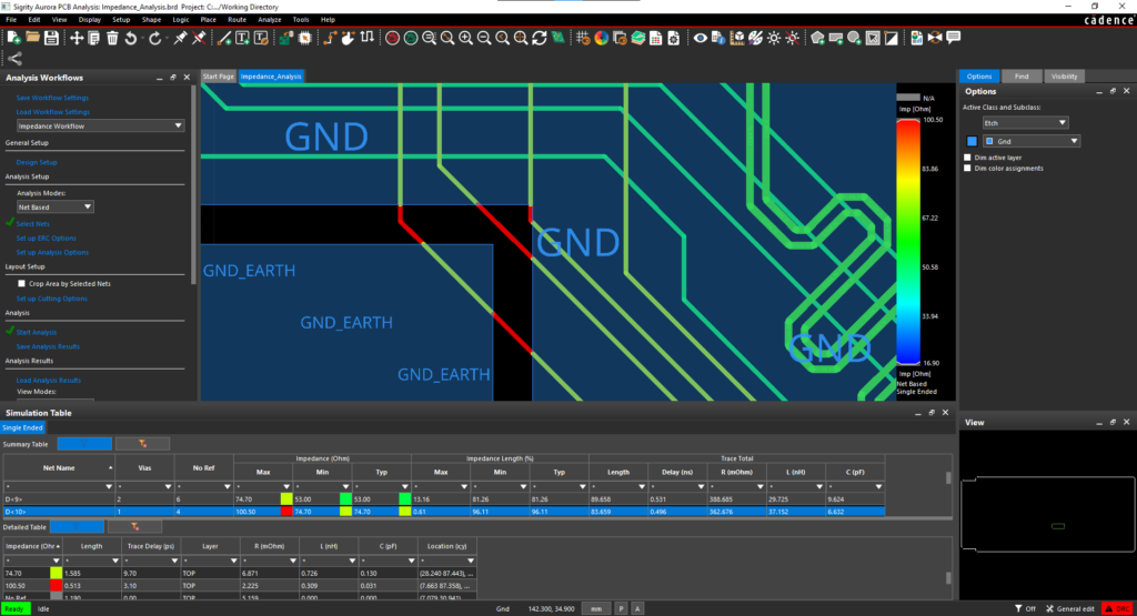
Larger pin count devices and shrinking pin pitches are forcing narrower than usual trace widths. This, in turn, means that single-ended and differential pair signals have to meander through the pin fields, sometimes with arcs. To make matters worse, pin fields are full of voids on reference planes, making impedance uncontrollable. By migrating to Allegro 17.2-2016, you can have access to new ways to manage impedance on signals in such areas. You can control impedance by adding trapezoidal shapes on parallel traces, provide tab count and pitch validation, and manage and delete tabs when traces are edited.
8. Allegro Sigrity, Better Together – Use “Sigrity verified” custom return path via structures in Allegro PCB Editor (Available in Allegro)
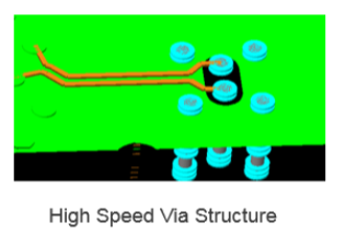
Allegro 16.6-2015 introduced six new return path via structures that you can add. With the Allegro 17.2-2016 release, you can incorporate customer pre-verified via structures to save time laying out the design and avoid any surprises during the post-layout verification process.
9. Ease-of-use Improvements (Available in OrCAD PCB Editor and Allegro)
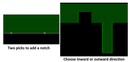
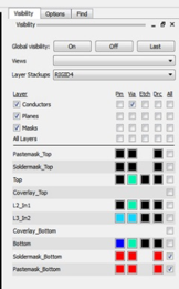
Making Allegro PCB Editor easy to use is an ongoing area of focus for us. In the Allegro 17.2-2016 release, we enhanced several features to reduce your time designing PCBs, to reduce your mouse clicks, and improve your customization capability. Now you can add customized commands to tool bars, and the Visibility Pane now allows designers to control layer content more quickly and more efficiently. There are several improvements in Constraint Manager, too.
10. New design rule checks (Available in OrCAD PCB Editor and Allegro)
As with previous releases, we continue to enhance in-design rules in PCB Editor. In addition to new rules for backdrilling and inter-layer checks for flex and rigid-flex designs, we added new drill DRCs as well as four acute angle detection rules. For drill DRCs, you may recall that a few releases ago, Allegro PCB Editor enabled dynamic pad suppression, and at that time we introduced a new DRC “hole to other objects.” This DRC associated with dynamic pad suppression was only enabled when a pad is marked for suppression. With this release, Allegro PCB Editor allows you to enable drill-based DRCs on holes that have pads on them – you can set and check for DRCs for padstacks whose pads are not marked for suppression. For angle-based rules we added these four new rules – minimum shape edge to edge; minimum line to pad angle; minimum line to shape angle; and minimum line to line angle.
To help you learn more about these new capabilities in the OrCAD/Allegro 17.2-2016 release and how you can benefit from them, we are launching this blog post series, 10 Top Reasons to Move Up to OrCAD/Allegro 17.2-2016 Release. Each week after this blog is published, we will delve into more details about each of the Top 10 reasons. Feel free to contact us if you have any questions, or would like to schedule a live demo with our technical experts.


