Rigid-flex PCBs combine both rigid and flexible circuits into a single design, offering mechanical flexibility to accommodate for the decreasing size of mechanical housing found in many of today’s products. These designs are widely used in applications where space savings, weight reduction, and durability are important, such as in aerospace, medical devices, and consumer electronics. While rigid-flex designs provide additional flexibility to adhere to your project specifications, additional complexities are introduced that must be addressed throughout the design process to produce a successful PCB including managing bends and layer stackups, ensuring reliability of mechanical stress points, and considering specialized manufacturing.
OrCAD X contains the functionality you need to create your rigid-flex PCB designs efficiently.
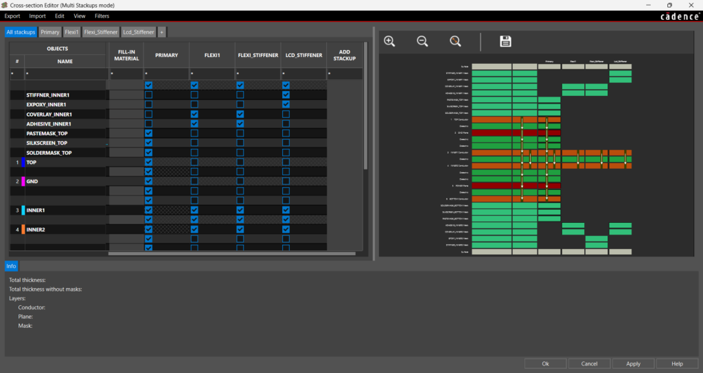
OrCAD X includes multiple stackup support to accommodate rigid-flex designs including support for industry standard Rigid-Flex and Surface Finishes classes such as Coverlay, Gold, Stiffener, and more. Easily define the layers, including non-conductor layers, that should be included in each stackup and review each stackup configuration.
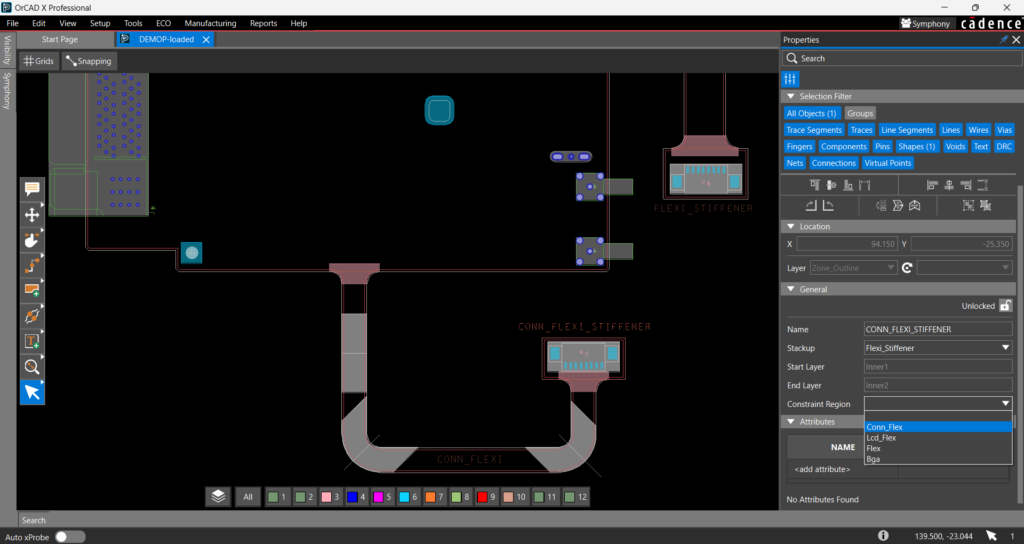
Efficiently create and define the flex and rigid zones on the PCB. OrCAD X allows you to easily define zones based on the board outline, assign stackups, and define constraint regions to ensure the different sections of your design adhere to the complex specifications required for your rigid-flex PCBs.
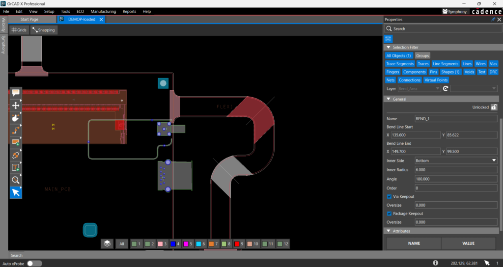
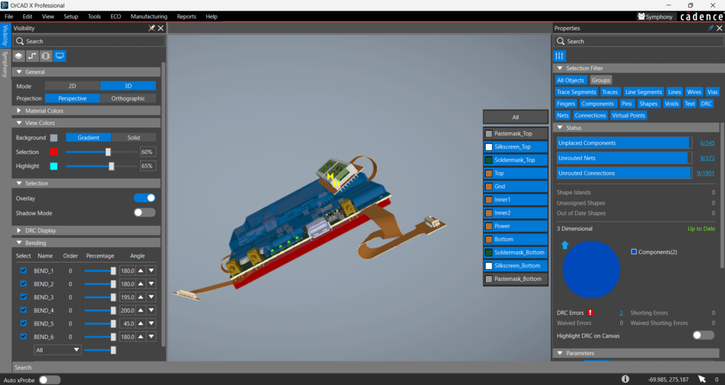
Easily create and manage bends in your rigid-flex designs to review a realistic representation of the final assembly. OrCAD X enables you to efficiently define the bend line, bend radius, angle, and side of the bend to verify the flex PCB.
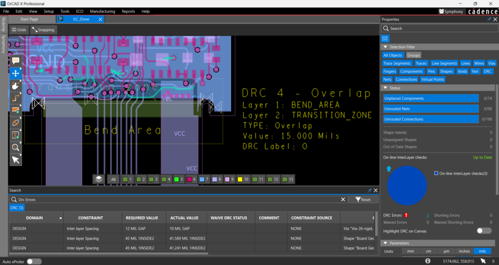
Assign different rules to flex and rigid portions of the design to adhere to specific design specifications and requirements. Inter-layer checks allow you to check geometries on two different Class/Subclasses to verify the special clearances or overlaps required in Rigid Flex designs due to the various masks, bend areas, and stiffeners.
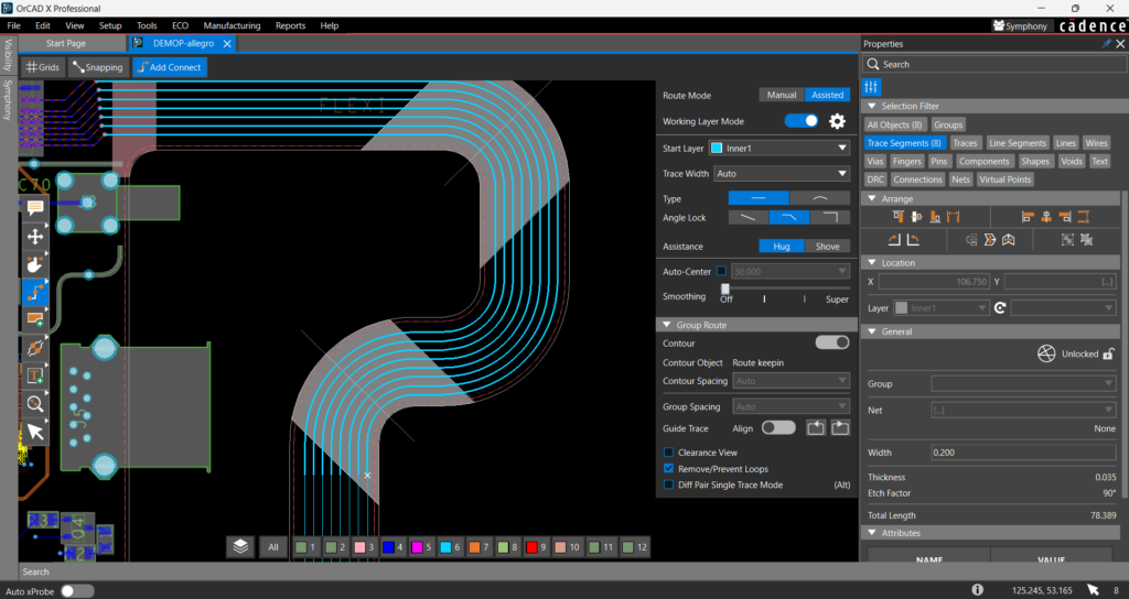
Efficiently route flex designs with the ability to contour traces to complex board geometries with OrCAD X. Easily select the object to contour your traces to and define your contour spacing. OrCAD X will automatically adhere to the unique board outline, allowing you to route your rigid-flex designs fast and accurately.
Let our team help you craft the perfect PCB design solution for your requirements. Contact us for more information.
See how OrCAD X can benefit your PCB design flow.