Every SPICE simulation needs to have an accurate source or input signal for a realistic analysis. A DC source, producing a constant voltage, is crucial for initial testing under ideal or nonideal conditions. PSpice allows you to quickly create the required DC source SPICE model for a realistic simulation.
This quick how-to will provide step-by-step instructions on how to create a DC source SPICE model in OrCAD PSpice.
To follow along, download the provided files above the table of contents.
How-To Video

Creating an Ideal DC Source
Step 1: Open the provided design in OrCAD PSpice Designer.
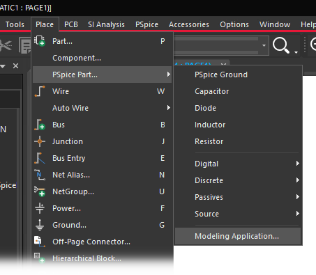
Step 2: Select Place > PSpice Part > Modeling Application from the menu.
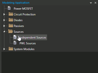
Step 3: In the Modeling application, expand Sources and select Independent Sources.
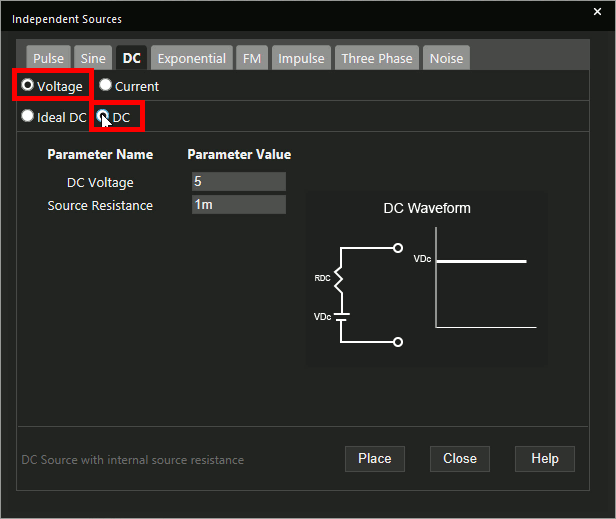
Step 4: The Independent Sources window opens. Select the DC tab.
Step 5: Select Voltage as the source type and Ideal DC as the DC type.
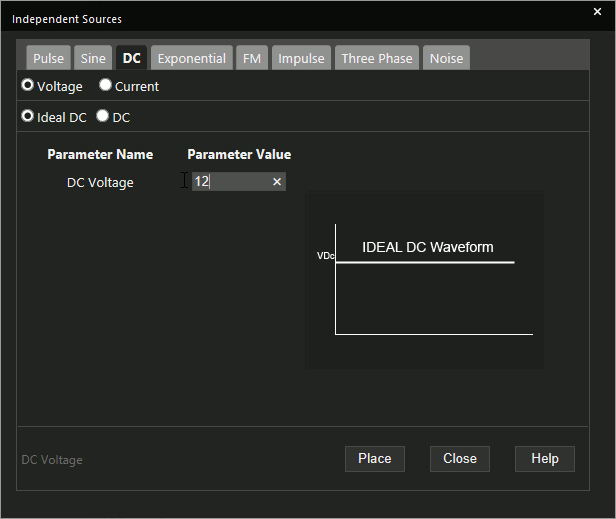
Step 6: Enter 12 for the DC voltage.
Learn how to determine the required parameters for a DC source SPICE Model here.
Step 7: Click Place to attach the source to your cursor.
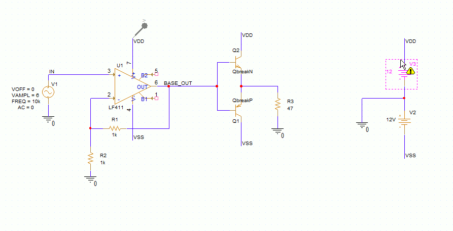
Step 8: Click to place the source in the schematic.
Running the Simulation
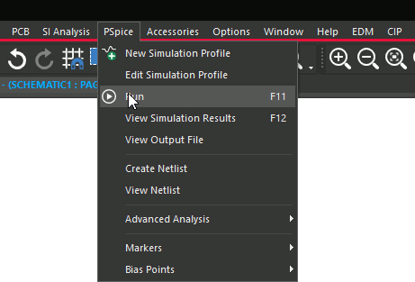
Step 9: Select PSpice > Run from the menu.
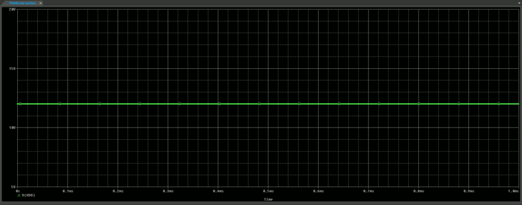
Step 10: View the simulation results. The power supply of the op-amp is a constant DC level, as expected.
Creating a Non-Ideal DC Source
Step 11: Back in the schematic, select the newly placed DC source and press Delete on the keyboard.
Step 12: Select Independent Sources from the Modeling Application.
Step 13: Select the DC tab.
Step 14: Select Voltage as the source type and DC as the DC type.
Note: This will create a DC source with internal resistance.
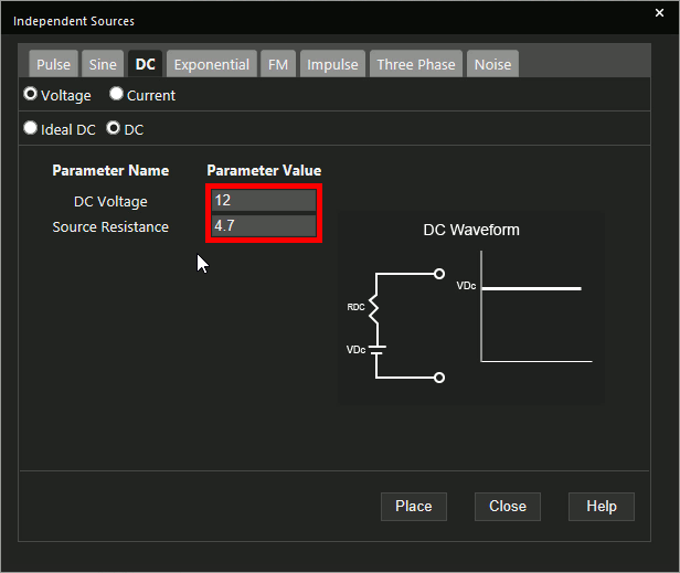
Step 15: Enter 12 for the DC Voltage and 4.7 for the Source Resistance.
Step 16: Click Place.
Step 17: Click to place the source in the schematic.
Step 18: Select PSpice > Run from the menu.
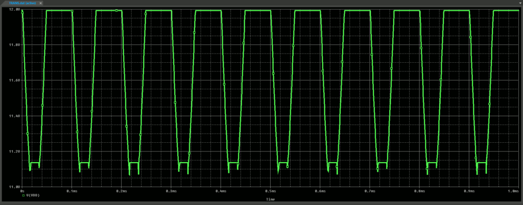
Step 19: View the simulation results. The source voltage now drops as the op-amp’s load resistor draws power.
Wrap Up and Next Steps
Quickly create the required DC source and simulate accurate circuit behavior with DC Source SPICE models in OrCAD PSpice. Test out this feature and more with a free trial of OrCAD. To learn more about determining the required parameters for a DC source SPICE Model in your circuit designs, view our blog here.

