 Ensuring PCB design documentation accuracy is crucial because it directly affects the electronic device manufacturing process, functionality, and reliability. Accurate documentation ensures that all design specifications are correctly communicated to manufacturers, reducing the risk of production errors, component mismatches, and assembly issues. This leads to higher quality products, minimizes costly rework or delays, and ensures that the final product meets performance and safety standards. The table below describes key steps to help ensure the accuracy of your PCB design documentation.
|
Steps To Ensure PCB Design Documentation Accuracy |
||
|
Step |
Explanation |
Importance |
|
Make sure connections, component values, and pin configurations match the design. |
Ensures that the design functions as intended and prevents errors in connectivity and component usage. |
|
|
2) Detailed Bill of Materials (BOM) |
Include detailed descriptions, part numbers, manufacturer information, alternate components, and required quantities. |
Provides a complete list of components needed for production, ensuring correct parts are ordered and available. |
|
3) Clear Layout Documentation |
Document layer details, dimensions, and via and pad sizes and ensure trace widths meet design rules and current-carrying requirements. |
Ensures the physical design meets electrical and mechanical requirements, preventing manufacturing issues. |
|
Run automated DRC using PCB design software to catch common errors and implement custom design rules. |
Identifies and corrects design errors early, reducing the risk of issues during manufacturing. |
|
|
5) Verification of Design Files |
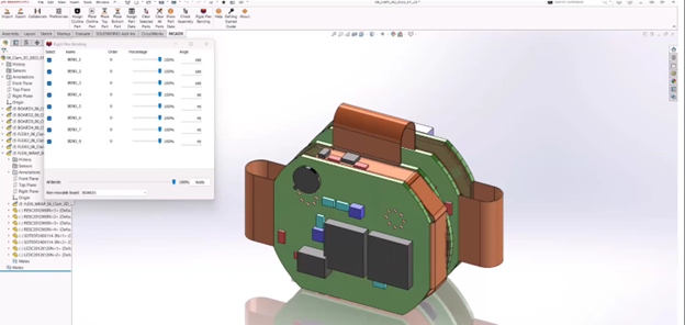
Check the integrity of design files, ensuring they are correctly generated and complete, and use 2D and 3D rendering for visual inspection. |
Ensures that the manufacturing files accurately represent the design, preventing production errors. |
|
6) Assembly Drawings |
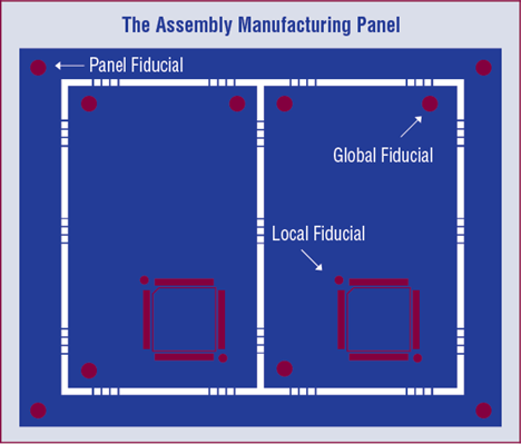
Indicate component placement and orientations clearly, and include special assembly instructions or notes. |
Provides clear guidance for assembly, reducing the risk of misplacement and incorrect component orientations. |
|
7) Test and Validation Procedures |
Build and test prototypes to validate the design, conduct thorough functional testing, and document any changes or revisions based on feedback. |
Verifies that the PCB functions as intended, allowing for correction of issues before full production. |
|
8) Peer Reviews |
Have the design reviewed by peers to catch errors and incorporate feedback from different team members. |
Catches errors the original designer may have missed, improving overall design quality. |
|
9) Version Control |
Use version control systems to track design changes and regularly back up all design files and documentation. |
Keeps a record of changes and ensures that the latest design is always used, preventing outdated designs from being used. |
|
10) Manufacturer Communication |
Communicate with the manufacturer for design for manufacturing (DFM) feedback and address any questions or clarifications to avoid misunderstandings. |
Ensures that the design is manufacturable and that any potential issues are resolved before production starts. |
PCB Design Documentation: OrCAD X Live DOC
It’s important to use reliable PCB CAD software to ensure accurate PCB design documentation. OrCAD X LiveDOC is a powerful tool that offers several features that contribute to maintaining high standards of PCB documentation accuracy:
- Real-time Synchronization: OrCAD X LiveDOC allows for real-time design data and documentation synchronization. Any changes made to the PCB design are automatically reflected in the documentation, ensuring that it is always up-to-date with the latest design changes.
- Automated Documentation Generation: The tool can automatically generate various types of documentation required for PCB design, such as schematics, BOM, and assembly drawings, thereby reducing the risk of human error and ensuring consistency across documentation.
- Version Control: OrCAD X LiveDOC includes version control features that track changes made to the design and documentation, which allows designers to revert to previous versions if needed and provides a clear history of changes.
- Collaboration Tools: The platform supports collaboration among team members by providing tools for commenting, reviewing, and approving design changes. The collaborative approach helps identify and correct errors early in the design process.
- Validation and Verification: OrCAD X LiveDOC includes validation and verification tools that check the design against predefined rules and standards. These tools identify potential issues and ensure that the design meets all requirements before finalizing the documentation.
- Customizable Templates: The tool offers customizable templates for various types of documentation, ensuring that all necessary information is included and presented consistently and professionally. Standardization helps reduce documentation errors and omissions.
- Integration with Other Tools: OrCAD X LiveDOC can integrate with other design and manufacturing tools, allowing for seamless data exchange and reducing the risk of errors caused by manual data entry or incompatible formats
- Enhanced Visualization: The tool provides enhanced visualization options for PCB designs, such as 3D views and interactive schematics, which enables a better design understanding and identifies potential issues that may not be obvious in 2D representations.
By leveraging these features, OrCAD X LiveDOC helps ensure that PCB design documentation is accurate, up-to-date, and consistent, ultimately leading to more efficient design processes and higher-quality final products. To best leverage these capabilities, it may be best to partner with an experienced industry leader that specializes in providing engineers with the tools, training and support needed to optimize PCB design and development.
EMA Design Automation is a leading provider of the resources that engineers rely on to accelerate innovation. We provide solutions that include PCB design and analysis packages, custom integration software, engineering expertise, and a comprehensive academy of learning and training materials, which enable you to create more efficiently. For more information on PCB design documentation and how we can help you or your team innovate faster, contact us.
