Placing Components
This lesson will demonstrate multiple options for placing components in a PCB layout in OrCAD X Presto.
To follow along, continue with the design from the previous lesson or download the starting materials from the Materials tab of this lesson.
 Open in New Window
Placing Components in OrCAD X Presto
Step 1: Select ECO > Quickplace Components from the menu.
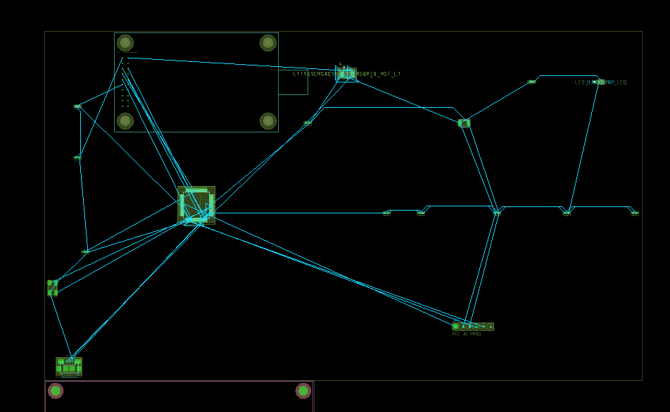
Step 2: All components in the circuit have been placed on the PCB canvas above the board.
Note: Quickplace places the components along the longest edge of the design outline. Use the mouse wheel or the minus (-) key on the keyboard to zoom out. Hold the middle mouse button to pan the view or use the arrow keys on the keyboard to move around the PCB canvas.
Configuring Automatic Cross-Probing and Cross-Placement
Step 3: Open the provided Capture_Tutorial.opj in OrCAD Capture.
Note: If your system has multiple monitors, put Capture in one window with Presto in another.
Step 4: In Capture, select Options > Preferences from the menu.
Step 5: Select the Miscellaneous tab.
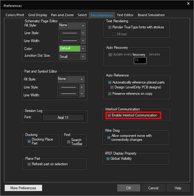
Step 6: Ensure the option for Enable Intertool Communication is checked. Click OK.
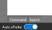
Step 7: In Presto, ensure that the Auto xProbe option at the bottom of the screen is switched on.
Step 8: Right-click on the Move icon in the toolbar and select Place.
Step 9: Select Series andpress X on the keyboard to hide the window.
Using Automatic Cross-Placement
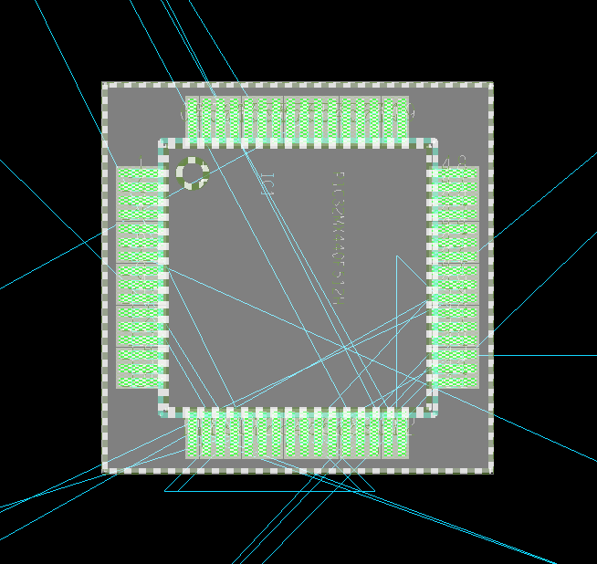
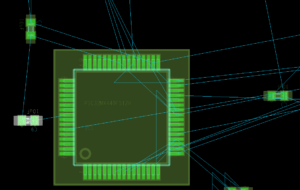
Step 10: In Capture, select IC1. The corresponding symbol is highlighted in Presto.
Step 11: Click the IC to select it. Use R on the keyboard to rotate. For this IC, press R three times to rotate to the proper orientation.
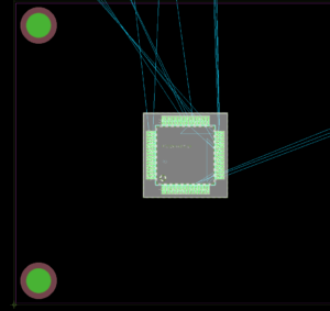
Step 12: Click to place the component on the PCB as shown.
Note: The component can be rotated after placement on the board by pressing R on the keyboard to with the component still selected.
Step 13: Back in OrCAD Capture, select JP1.

Step 14: JP1 is highlighted automatically in OrCAD X Presto. Click to select the component and click again to place on the PCB as shown.
Step 15: Expand the OrCAD X Presto window to full screen.
Placing Components in Groups
Step 16: Press X on the keyboard to bring the Placement window up.
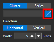
Step 17: Select Cluster and Expand in the placement window.
Step 18: The Search panel opens. Enter 3.3V into the search bar and press Enter.
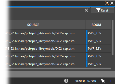
Step 19: View the search results. Capacitors C4-C8 are listed. These capacitors are members of a room with name “PWR_3.3V.” The room property can be viewed in the search table.
Step 20: Select capacitor C4, hold Shift and select C5, C6, C7, and C8;or click and drag the selection.
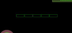
Green outlines appear on the board to indicate the component locations. The components are currently in a horizontal clustering.
Step 21: Select Vertical in the placement window.
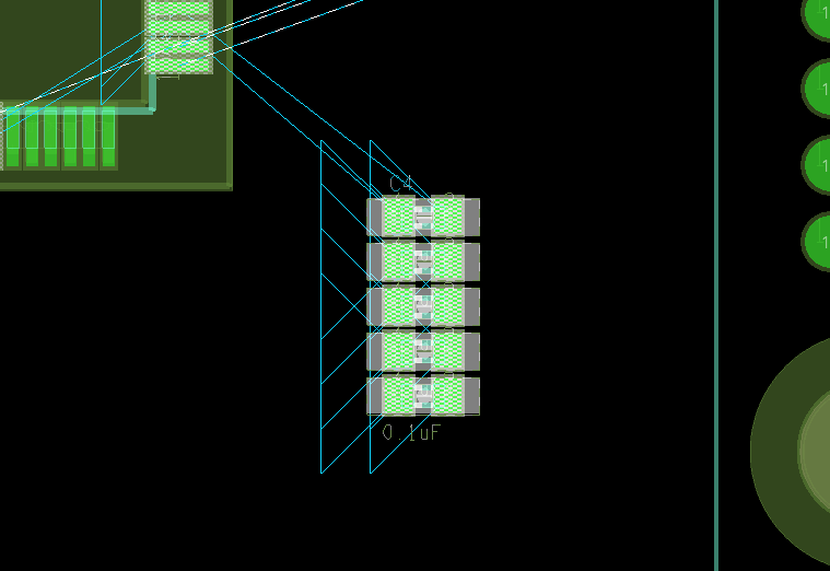
Step 22: Click to place the capacitors in the schematic. The capacitors are placed vertically on the PCB canvas as designated in the placement window.
Placing Components by Search
Step 23: Clear the Search panel and double-click the table entry for capacitor C1 to highlight the part on the canvas.
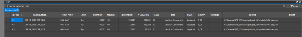
Step 24: In the Properties panel for C1, select the hyperlink for the part number. The part number is automatically entered into the search field, and components with the same part number are listed.
Step 25: Single-click the reference designator to place the part.
Step 26: Click to place the part on the board.
Step 27: Repeat steps 25 and 26 for capacitors C3 and C9.
Placing the Remaining Components
Step 28: Select Series in the placement window and press X on the keyboard to hide the window.
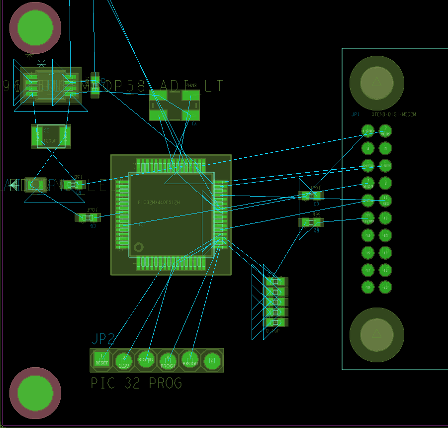
Step 29: Click to select each remaining component above the board, except the USB Micro B connector X1, and click to place within the board outline as shown.
Note: Use R on the keyboard to rotate components as needed or the rotate left and rotate right icons in the placement window.
Step 30: Press Escape on the keyboard to end placement, then choose Select from the toolbar.
Placing Components by Coordinates
Step 31: In the Properties panel, under Status, view the unplaced components. Unplaced components are shown graphically as a bar and as a ratio.
Step 32: Click the ratio of unplaced components. The search panel opens displaying the unplaced components for easy access.
Step 33: Click the USB-B connector, X1, reported in the Search Panel. You are brought to the location on the PCB and the component is selected.
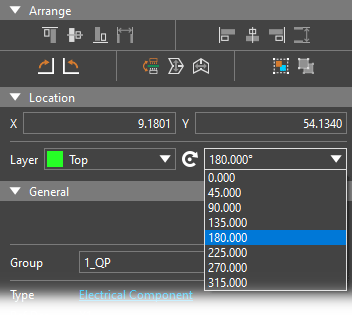
Step 34: In the Properties Panel, select 180° from the rotation drop-down.
Note: The rotate left and rotate right icons in the Properties Panel can also be used to rotate components on the PCB.
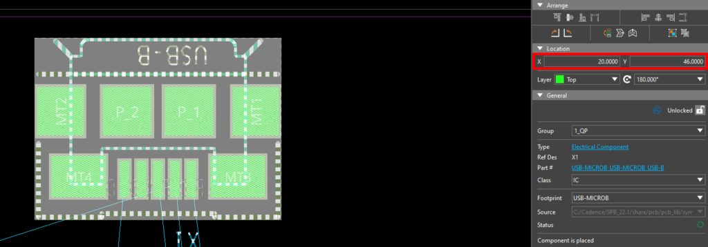
Step 35: Enter 20 for the X location and 46 for the Y location.
Step 36: Select the lock icon to lock the connector into place.
Note: Coordinates and orientation may be defined for critical components in the design manually if a component’s placement is specified by the mechanical engineer. Be sure to lock these components in place to guarantee accuracy throughout the PCB layout.
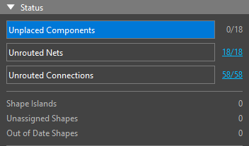
Step 37: In the Properties panel, under Status, confirm the number of unplaced components is indicated as 0.
