Creating Manufacturing Documentation
This lesson will demonstrate how to create manufacturing documentation with LiveDoc in OrCAD X Presto.
To follow along, continue with the design from the previous lesson or download the starting materials from the Materials tab of this lesson.
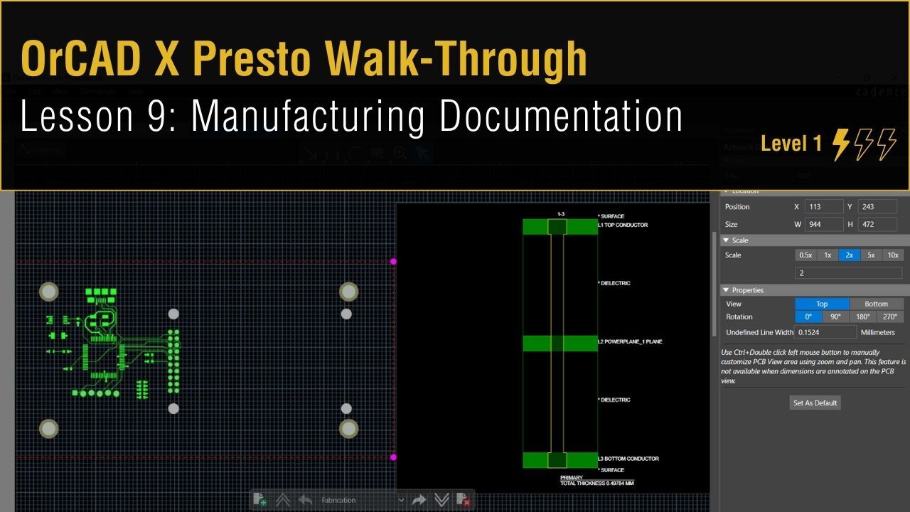 Open in New Window
Adjusting Silkscreen Text
Note: Before manufacturing documentation is created, the silkscreen should be adjusted.
Step 1: In the Selection Filter, disable All Objects and enable Text.
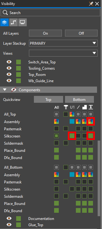
Configuring Visibility Settings in OrCAD X Presto
Step 2: In the Visibility panel select the Layers mode.
Step 3: Under Components, disable visibility for Pin_Number and enable visibility for the following:
- Silkscreen Text
- Silkscreen Reference Designator
- Assembly Textfor the Top components
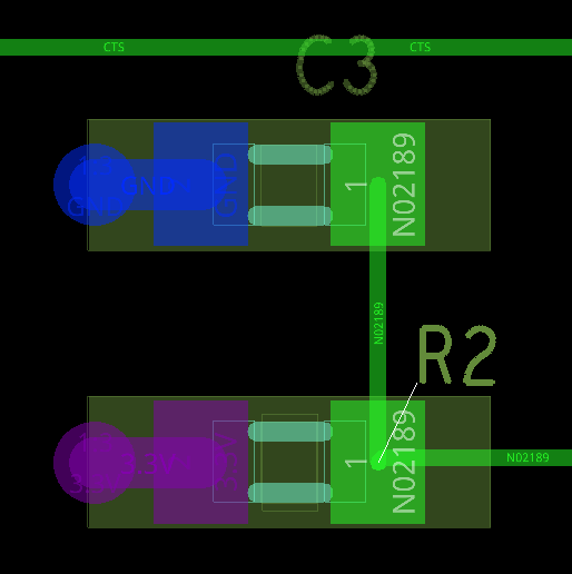
Step 4: Click and drag to adjust the silkscreen and reference designators so they are in the same orientation and on top of their respective components.
Note: Press R on the keyboard to rotate as needed. Press Delete to delete any unnecessary text.
Step 5: For U1 and the LED, change the reference designator text block to 17 in the Properties panel.
Creating Manufacturing Documentation
Step 6: Select Manufacturing > LiveDoc > Create New from Template from the menu.
Note: To access existing LiveDoc data, select Manufacturing > LiveDoc > Open from the menu. LiveDoc opens in the same window of Presto. The Fabrication page is automatically generated and opened containing a top and bottom view of the board, as well as a stackup chart and stackup table.
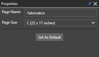
Step 7: View the Properties panel on the right side of LiveDoc. The Properties panel lets you set the page name and size for the documentation.
Adding Drill Documentation
Step 8: Select the top view of the board in the top left. Press Delete on the keyboard.
Note: This view will be added to its own page later.
Step 9: Select the bottom view of the board in the bottom left. Press Delete on the keyboard.
Step 10: Select Place to expand the Placement panel. This panel contains templates for several PCB views including artwork, fabrication, and assembly. The panel can be undocked like any panel in Layout.
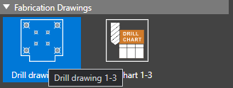
Step 11: Select Drill Drawing 1-3.
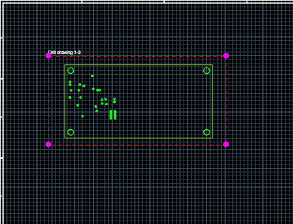
Step 12: Click to place the drill drawing in the canvas.
Step 13: With the drill drawing selected, in the properties panel set the scale to 2x. Click and drag to adjust the drawing as needed.
Note: With the artwork selected, the Properties Panel allows you to efficiently modify the following:
- Title
- Size and Position
- Scale
- Rotation
Step 14: Click and drag the text “Drill Drawing 1-3” to move it to the bottom-center of the drawing.
Step 15: With the text selected, in the Properties panel, change the font size to 25.
Step 16: Open the Place panel and select Drill Chart 1-3.
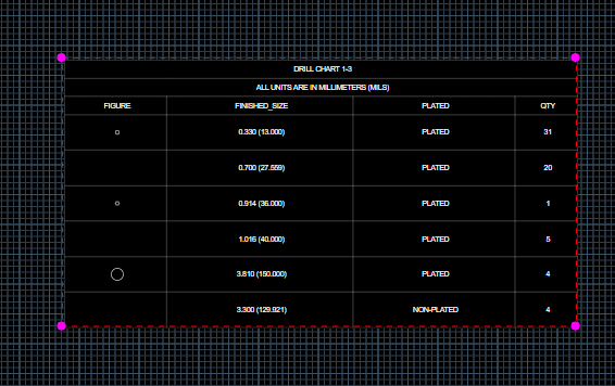
Step 17: Click and drag to draw the drill chart. Release the mouse button when the chart is about the height of the drawing.
Step 18: Select the chart. In the Properties panel, change the font size to 25.
Note: The Properties panel allows you to configure various aspects of the drill chart including:
- Sorting method
- Columns included (tolerance, tool size, etc.)
- Units
- Font
- Alignment
- Size and position
- Title
Step 19: Select the existing stackup chart. In the Properties panel, change the font size to 20.
Note: In the Properties panel, the stack up chart can be customized to include:
- Layer thicknesses
- Material names
- Tolerances
Step 20: Select the existing stackup table. In the Properties panel, change the font size to 25.
Adding Dimensions

Step 21: Click to select the Linear Dimension mode from the toolbar.
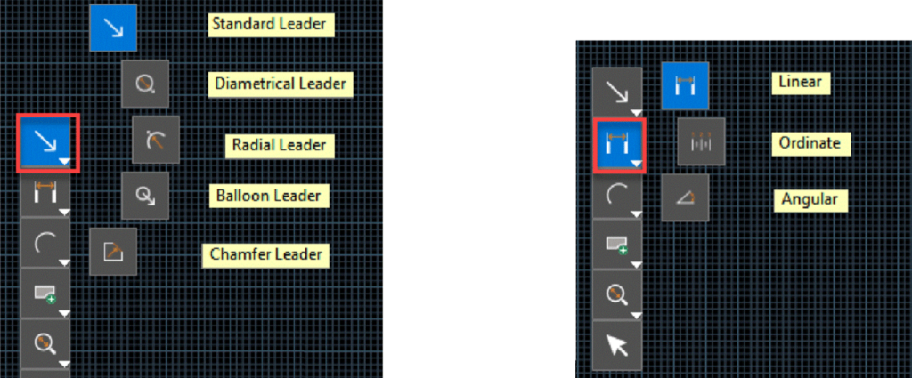
Note: Other dimension options are also available, including:
- Ordinate
- Angular
- Standard Leader
- Diametrical Leader
- Radial Leader
- Balloon Leader
- Chamfer Leader
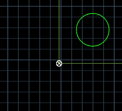
Step 22: Click to select the bottom-left corner of the board in the drill drawing.
Note: The selection crosshairs turn white when a selectable object is under the cursor.
Step 23: A dimension object is created. Click to select the bottom-right corner of the board.

Step 24: Click to select the position of the dimension to place it.
Note: By default, dimensions are printed in mils. This will be changed later.
Step 25: Select the Select mode from the toolbar or press Escape on the keyboard.
Step 26: Select the width dimension. In the Properties panel, set the Primary Units to mm and the font size to 20.
Note: The dimension changes to 100mm.
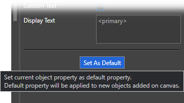
Step 27: Select Set as Default.
Note: This will configure the units and font size for future dimensions.
Step 28: Click to select the Linear Dimension mode from the toolbar.
Step 29: Click to select the top-left corner of the board followed by the bottom-left corner of the board to dimension the board height.
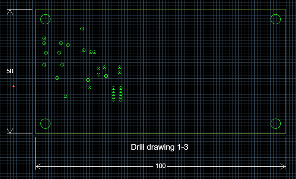
Step 30: Click to select the position of the dimension to place it.
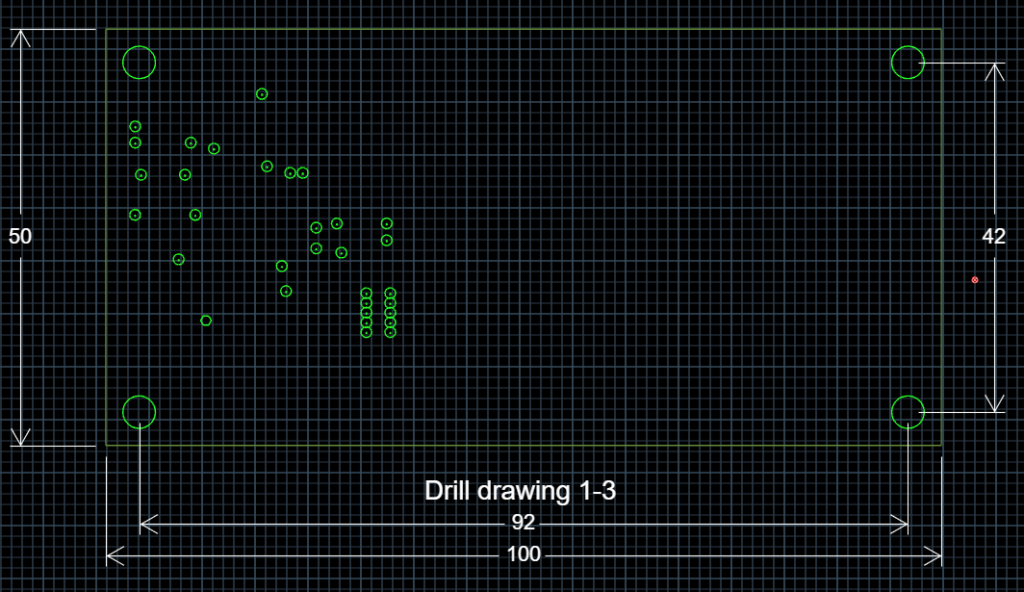
Step 31: Click to place dimensions between the mounting holes on each edge of the board.
Step 32: Press Escape or select the Select mode from the toolbar when finished.
Modifying Assembly Drawings

Step 33: In the navigation bar at the bottom of LiveDoc, select Assembly from the Select Page dropdown.
Note: The Assembly page opens containing an assembly top and assembly bottom drawing by default.
Step 34: Select the Assembly Bottom drawing in the bottom left and press Delete on the keyboard.
Step 35: Select the Assembly Top drawing. In the Properties panel, set the Scale to 3.
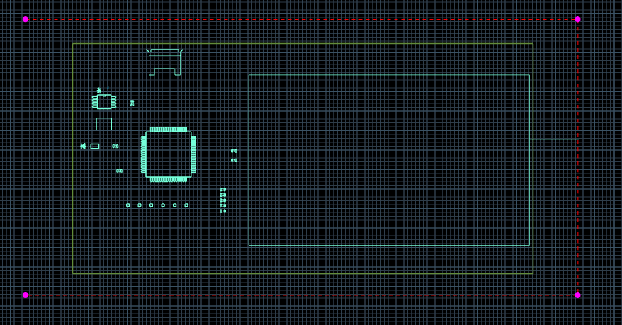
Step 36: Click and drag to move the drawing closer to the center of the board.
Adding Additional Drawings

Step 37: Select Add Page in the navigation bar.
Step 38: The new page opens automatically. In the Properties panel, set the page name to TOP.
Step 39: Open the Place panel and select TOP under Artwork to place the top film.
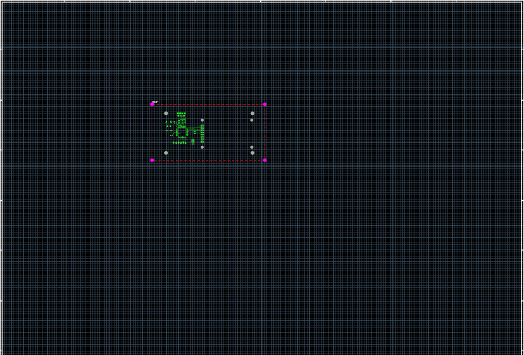
Step 40: Click to place the film in the center of the page.
Step 41: Select the artwork film. In the Properties panel, enter 3 for the Scale.
Step 42: Open the Visibility panel. Enable visibility for the Design Outline under Geometries.
Step 43: Click and drag the text “TOP” to move it to the bottom-center of the drawing.
Step 44: With the text selected, in the Properties panel, change the font size to 25.
Step 45: Repeat steps 37-44 with the following films:
- POWERPLANE_1
- BOTTOM
- SILKSCREEN TOP (labeled SSTP)
- SOLDERMASK TOP (labeled SMTP)
- SOLDERMASK BOTTOM (labeled SMBT)
- SOLDERPASTE TOP (labeled SPTP)
Step 46: Select File > Export PDF.
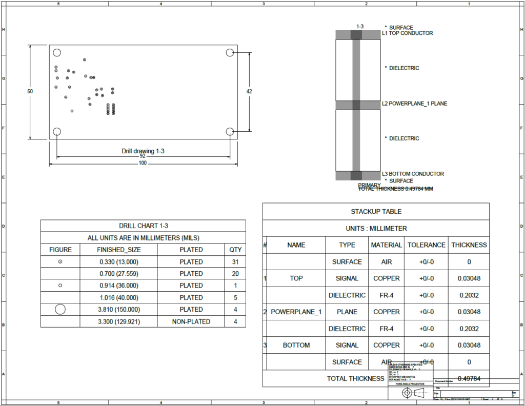
Note: A PDF can be quickly generated and shared with co-workers for efficient design review and collaboration.
Step 47: Close the PDF.
Step 48: Select File > Save as Template.
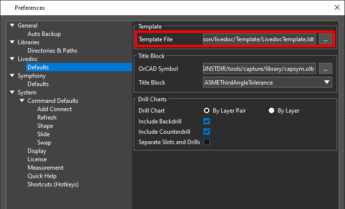
Note: Here you can provide a name for the template and save the document configuration for efficient reuse in future designs. Templates and titleblocks can be configured by selecting Edit > Preferences > LiveDoc > Defaults from the OrCAD X Presto menu.
Step 49: Click Cancel.
Note: Any changes made in the PCB canvas are automatically updated in the LiveDoc documentation in real-time, eliminating documentation errors and improving efficiency.